
Importing 3D Data
Now that we have discussed using 2D reference data, we will cover how to use 3D model data within your Revit project. There are many valid reasons for modeling outside of Revit, including software expertise, availability of content or generation, and optimization of complex geometry. The following sections will explore some situations in which model data can be shared between programs, including
- Imported data as a mass
- Imported data as a face
- Imported data as an object
Imported Data as a Mass
In Chapter 9, “Advanced Modeling and Massing,” you will learn more about harnessing the impressive modeling tool set in Revit's conceptual massing environment; however, the fast and flexible process of design may lead architects to a tool in which they have more expertise or comfort. This type of massing design workflow is supported in Revit under the following conditions:
- Masses require volumetric geometry to calculate volume, surface area, and floor area faces.
- Finely detailed complex geometry should be avoided as the Host By Face tools may not be able to generate meaningful objects.
Refer to Revit Architecture's help system for even more details on using imported geometry in a mass family.
This example demonstrates the process of creating an in-place mass by linking an external model—in this case, a SketchUp model. You can download the file c08-Mass.skp from the book's web page.
- Start a new Revit project. From the Massing & Site tab, select In-Place Mass from the Conceptual Mass panel.
- Name the new mass family SKP Mass and click OK.
- Switch to the Insert tab and select Link CAD from the Link panel; be sure to switch your file type filter to *.skp files.
- Navigate to the SKP file downloaded from the book's web page and set the following options:
- Colors: Invert
- Layers: All
- Import Units: Auto-Detect
- Positioning: Auto – Center To Center
- Place At: Level 1
- Click Open to complete the link process.
- Click Finish Mass in the In-Place Editor panel.
Now that a new mass has been created, you can assign mass floors and begin to see calculated results in schedules of masses and mass floors. (Refer to Chapter 9 for more information on these processes.) Calculation of volumes, perimeters, and mass floor areas will work well in this workflow, but be careful when using imported model geometry with the By Face tools because face updates will likely be more difficult for Revit to maintain than with native Revit massing.
Using linking instead of importing enables continued iteration of the form in the original software. In the case of this example, you may edit the original file in Google SketchUp, which is available as a free download from http://sketchup.google.com, or you can download the file c08-Mass-2.skp from the book's web page.
If you modify and save the original SKP file yourself, save, close, and reopen the Revit project. Alternatively, open the Manage Links dialog box, select the SKP file, and click Reload. If you want to use the alternate file downloaded from the book's web page, use the following steps:
- Open the Manage Links dialog box from the Insert tab.
- Select the SKP file and click Reload From.
- Navigate to the file c08-Mass-2.skp and click Open.
- Click OK to close the Manage Links dialog box.
With the modified mass loaded, notice the changes in the Mass Schedule and Mass Floor Schedule.
Imported Data as a Face
Similar to the data as mass workflow, externally modeled data can be used as a driver for more complex forms. An example might be the need to generate a complex curved roof surface. We will demonstrate this workflow using Rhino by McNeel (www.rhino3d.com) to generate a shape, link the shape into Revit, and create a roof by face on the shape.
As shown in Figure 8.10, a complex surface is generated in Rhino from drawing two curves and using the Extrude Curve Along Curve tool. Note that some reference geometry was exported from a Revit model to DWG and linked into this study in Rhino.
FIGURE 8.10 Curves for a complex surface in Rhino

A flat surface model is enough to generate a roof by face in Revit; however, it may be difficult to see the imported surface, so use the Extrude Surface tool to give it a thickness. Once the surface is complete (Figure 8.11), select only the double-curved geometry, choose File ![]() Export Selected Objects, and choose the .sat file extension. SAT will generate the cleanest geometry for curved solids and surfaces.
Export Selected Objects, and choose the .sat file extension. SAT will generate the cleanest geometry for curved solids and surfaces.
FIGURE 8.11 Completed complex surface in Rhino

You can download the Rhino file (c08-Roof-Face.3dm) and SAT export (c08-Roof-Face.sat) from this book's web page. You can also download the sample Revit project and continue the process as follows:
- Open the file c08-Roof-by-Face.rvt and make sure you are in the 3D view named 00-Start.
- On the Massing & Site tab, choose In-Place Mass and name it Rhino Roof.
- Switch to the Insert tab and select Link CAD. Switch to filter your file type to *.sat and navigate to the c08-Roof-Face.sat file downloaded from the book's web page.
- Set the placement options as follows:
- Positioning: Auto – Origin To Origin
- Place At: Level 1
- Import Units: Inch
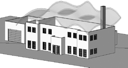
- Click Open to complete the link and close the dialog box, and then click the Finish Mass button in the ribbon. The mass should be seen above the tops of the walls in the Revit model, as shown in Figure 8.12.
FIGURE 8.12 Complex surface linked as an in-place mass
- Return to the Massing & Site tab and select the Roof tool from the Model By Face panel. Choose the Basic Roof: Generic 12″ from the Type Selector, and click the top face of the mass created in the previous steps. Click the Create Roof button in the ribbon to complete the command and the roof will be generated along the mass surface, as shown in Figure 8.13.
FIGURE 8.13 Roof By Face applied to the mass with linked SAT geometry
- Select all the perimeter walls—using the Tab key or Ctrl to add individually to the selection.
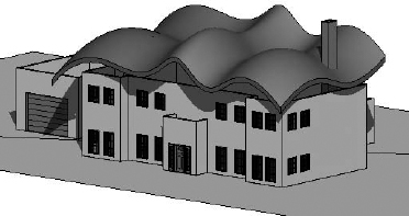
- Select the Attach Top/Base tool from the Modify | Walls tab, set the Top option in the Options Bar, and pick the roof by face created in step 6. The walls will connect to the underside of the complex roof shape, as shown in Figure 8.14.
FIGURE 8.14 Completed roof with tops of walls attached

The original shape can be edited in the originating software and will update in Revit via the link if the original exported SAT file is overwritten. To update the roof based on the newly modified massing geometry, select the roof and click the Update To Face button in the Modify | Roofs tab.
Imported Data as an Object
Yet another derivation of the reference data workflow supports the use of linked model geometry for specific instances of building components. Examples of this scenario might include a complex canopy structure being designed in SolidWorks or a building's structural framing being modeled in Bentley Structural Modeler. The workflow is again similar to that of using imported data as a mass or face; however, the file format will help you control the component's visualization in Revit. In the previous exercise, we used an SAT format to transfer complex curved geometry from Rhino to Revit; however, a limitation of an SAT file is that the geometry contains only one layer, making it impossible to vary material assignments for different components of the design. We recommend using a solids-based DWG, DGN, or DXF file format, which will maintain a layer structure in most cases.
In the following example, you will create an in-place structural framing component that will act as a placeholder for a consultant's structural model created in Bentley Structural Modeler. You will be using the file c08-Framing.dgn, which you can download from the book's companion web page: www.sybex.com/go/masteringrevit2012.
- Launch Revit and start a new project using the default.rte template.
- Switch to the Home tab and choose Component
 Model In-Place. Set the category to Structural Framing. For other scenarios, remember that some categories cannot be cut in Revit.
 - Name the new in-place model DGN Structure.
- From the Insert tab, select Link CAD.
- Change the Files Of Type option to DGN Files (*.dgn) and navigate to the downloaded file.
- Set the following options and click Open:
- Current view only: Unselected
- Colors: Black and White
- Layers: All
- Positioning: Auto – Origin To Origin
- Place At: Level 1
- Click Finish Model in the In-Place Editor panel to complete the process.
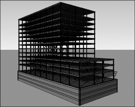
Switch to a 3D view, and you should see the entire contents of the DGN model (Figure 8.15). Because the linked content was created as a structural framing model, the linked data will be displayed similarly to any other structural framing element in Revit. Examine the linked model in different plans and sections to observe this behavior.
FIGURE 8.15 DGN structural model linked into Revit
Utilizing linked models in DWG, DGN, or DXF format also allows you to modify the graphic representation of the elements within Revit. To adjust these settings, do the following:
- Select the Manage tab, click Object Styles, and switch to the Imported Objects tab.
- Find your linked file, expand it to expose the layers or levels included in that file, and modify the graphic settings as desired.
When you are using linked model data for custom components, the consistency of the data you bring into Revit from other programs depends on the ability of that software to generate organized information. Some programs utilize layers, and some don't. Recognizing this difference will give you the best opportunity for success in coordination through interoperability.