
Presenting with 3D Views
In addition to using 2D views such as plans, sections, and elevations to convey your design intent, you can present the 3D model in a variety of ways. In Chapter 12, we discussed the methods for creating analytic and photorealistic visualizations; however, this section will help you to establish a new repertoire of presentation techniques for design and construction documents.
Orienting to Other Views
A quick and easy way to create more useful 3D views is by utilizing the Orient To View command. This command, which is somewhat hidden within the ViewCube, allows you to create a 3D view that mimics the settings of a 2D view.
In the following exercise, you will continue to use the c20-Sample-Building.rvt file. You will first adjust the view range settings for the floor plans and then create a 3D view for each level. Finally, you will assemble the views on a sheet to complete the presentation.
- Select Level 1 from the Project Browser and go to the Properties palette to examine the view properties. Click the Edit button in the View Range property.
- In the View Range dialog box (Figure 20.13), change the Top value under Primary Range to Level Above and set the corresponding offset value to −1′−8″ [−500 mm]. Repeat this step for Level 2.
FIGURE 20.13 Adjust the Top values for the plan's view range.
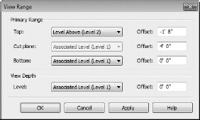
Note that although you are changing the top of the view range of the floor plans, you will not see any difference in their graphic display.
- Right click on the default 3D view in the Project Browser and create two duplicates. Rename the duplicate views as Box-Level 1 and Box-Level 2.
- Activate the view Box-Level 1 and right-click on the ViewCube. Select Orient To View
 Floor Plans Floor Plan: Level 1, as shown in Figure 20.14.
The view will be set to a plan orientation, but more importantly, a section box has been enabled that matches the extents of the Level 1 plan view. Try orbiting the view to see the results (Figure 20.15).
FIGURE 20.14 Orient a 3D view to any other 2D view.
FIGURE 20.15 A 3D view after being oriented to a plan view

- Right-click on the ViewCube and select Orient To A Direction Southwest Isometric.
- Repeat steps 4 and 5 for Level 2.
- Create a new sheet using the C size title block and drag the Box-Level 1 and Box-Level 2 onto the sheet.
Place the Box-Level 2 view directly above the Box-Level 1 view and you'll notice that the views will align vertically. Revit allows you to align model views of various types on sheets as long as they are the same scale. This does not work for drafting views or perspective views.

We showed you how to create 3D representations of each level within your design using the Orient To View command. There is also a free Revit plug-in to automate this process that was developed specifically for construction coordination by DPR Construction. The installation can be downloaded from http://modelslicer.dpr.com.
Annotating 3D Views
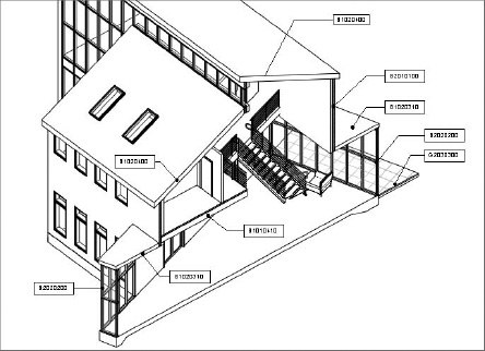
A new feature in the Revit 2012 platform is the ability to lock a 3D orthographic view and then add text and tags like you would in a 2D view. This functionality is quite simple to implement. In the example shown in Figure 20.16, a section box was first applied to a 3D view.
FIGURE 20.16 Annotation can be applied to a 3D view with locked orientation.
In any orthographic 3D view, you will find the Lock/Unlock 3D View button in the view shortcut bar as shown in Figure 20.17. Once you lock the view, you can begin to add tags, text, and dimensions in some circumstances, but you cannot change the orientation of the view unless it is unlocked.
FIGURE 20.17 The 3D view can be locked from the View Control Bar.

Once you have added annotation to a view, you may need to rotate the view. Return to the locked view tool and click Unlock View. You are now free to orbit the 3D view; however, the annotation you placed temporarily disappears. There are two ways to reset the orientation. If you wish to return the view to the originally saved orientation, click Restore Orientation And Lock View. The annotation will reappear.
If you decide to keep the new orientation, you can click Save Orientation And Lock View, but you will receive a warning about losing all of the previously stored annotation (Figure 20.18). If you click OK, you will need to replace all the annotations in the newly locked view.
FIGURE 20.18 Saving a new view orientation will remove any previously placed 3D annotations.
