Corridors are not just for roads. Once you have the basics from this chapter down, your ingenuity can take hold.
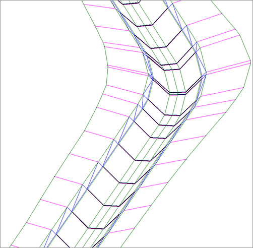
Corridors can be used for far more than just road designs. You explore some more advanced corridor models in Chapter 10, but there are plenty of simple, single-baseline applications for alternative corridors such as channels, berms, streams, retaining walls, and more. You can take advantage of several specialized subassemblies or build your own custom assembly using a combination of generic links. Figure 9-42 shows an example of a stream corridor.
Figure 9-42: A simple stream corridor viewed in 3D built from the Channel subassembly and a generic link subassembly
One of the subassemblies discussed in Chapter 8 is the Channel subassembly. The following exercise shows you how to apply this subassembly to design a simple stream:
1. Open the Corridor Stream.dwg file. Note that there is an alignment that represents a stream centerline, a profile that represents the stream normal water line, and an assembly created using the Channel and LinkSlopetoSurface subassemblies.
2. Change to the Home tab and choose Corridor Create Simple Corridor on the Create Design panel. The Create Simple Corridor dialog opens.
3. Name your corridor Stream Channel. Click OK.
4. Follow the prompts, and pick the Stream CL alignment, the Stream NWL profile, and the Project Stream assembly. The Target Mapping dialog will appear after all objects have been picked.
5. In the Target Mapping dialog, choose the Existing Ground surface for all surface targets. Keep the default values for the additional targets. Click OK to dismiss the dialog.
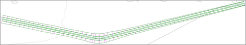
6. The stream corridor will build and will look similar to Figure 9-43. Select the corridor and choose Corridor Section Editor from the Modify panel. Navigate through the stream cross sections. When you are finished viewing the sections, dismiss the dialog by clicking the X on the Close panel.
Figure 9-43: The completed stream corridor
This corridor can be used to build a surface for a TIN-to-TIN volume calculation or can be used to create sections and generate material quantities, cross-sectional views, and anything else that can be done with a more traditional road corridor.
Creating a Pipe Trench Corridor
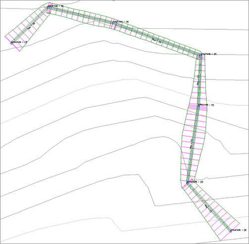
Another use for a corridor is a pipe trench. A pipe trench corridor is useful for determining quantities of excavated material, limits of disturbance, trench-safety specifications, and more. This graphic shows a completed pipe trench corridor:

One of the subassemblies discussed in Chapter 8 is the TrenchPipe1 subassembly. The following exercise leads you through applying this subassembly to a pipe trench corridor:
1. Open the Corridor Pipe Trench.dwg file. Note that there is a pipe network, with a corresponding alignment, profile view, and pipe trench assembly. Also note that there is a profile drawn that corresponds with the inverts of the pipe network.
2. Change to the Home tab and choose Corridor Create Simple Corridor. Name the corridor Pipe Trench. Click OK.
3. Follow the prompts, press ↵, and pick the Pipe Centerline alignment from the list, the Bottom of Pipe profile, and the Pipe Trench assembly as your corridor components. Once these selections are made, the Target Mapping dialog appears.
4. In the Target Mapping dialog, choose Existing Ground as the target surface. Click OK.
5. The corridor will build. Select the corridor and choose Corridor Section Editor from the Modify panel. Browse the cross sections through the trench.
6. When you are finished viewing the sections, dismiss the dialog by clicking the X on the Close panel.