
In Civil 3D, a site is a collection of parcels, alignments, grading objects, and feature lines that share a common topology. In other words, Civil 3D objects that are in the same site are related to, as well as interact with, one another. The objects that react to one another are called site geometry objects.
Best Practices for Site Topology Interaction
At first glance, it may seem the only uses for parcels are subdivision lots, and therefore you may think you need only one site for your drawing.
However, once you begin working with parcels, you’ll find features like dynamic area labels to be useful for delineating and analyzing soil boundaries; paving, open space, and wetlands areas; and any other region enclosed with a boundary. The automatic layer enforcement of parcel object styles adds to the appeal of using parcels. Using additional types of parcels will require you to come up with a site management strategy to keep everything straight.
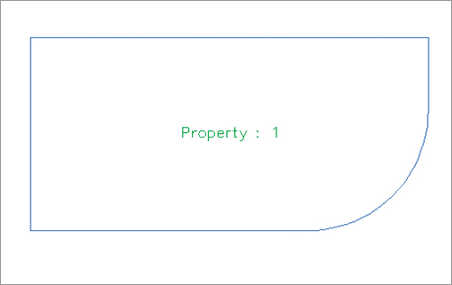
It’s important to understand how site geometry objects react to one another. Figure 5-1 shows a typical parcel that might represent a property boundary.
Figure 5-1: A typical property boundary
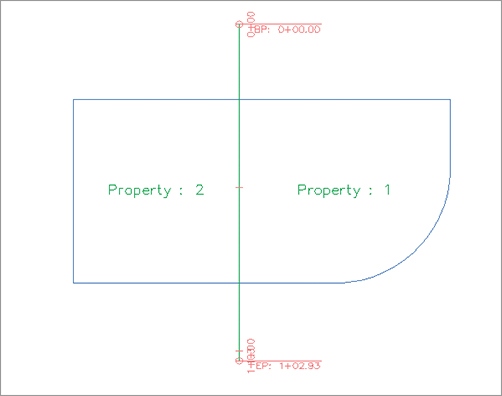
When an alignment is drawn and placed on the same site as the property boundary, the parcel splits into two parcels, as shown in Figure 5-2.
Figure 5-2: An alignment that crosses a parcel divides the parcel in two if the alignment and parcel exist on the same site.
You must plan ahead to create meaningful sites based on interactions between the desired objects. For example, if you want a road centerline, a road right-of-way (ROW) parcel, and the lots in a subdivision to react to one another, they need to be in the same site (see Figure 5-3).
Figure 5-3: Alignments, ROW parcels, open space parcels, and subdivision lots react to one another when drawn on the same site.

The alignment (or road centerline), ROW parcel, and lots all relate to one another. A change in the centerline of the road should prompt a change in the ROW parcel and the subdivision lots.
If you’d like to avoid the interaction between site geometry objects, place them in different sites. Figure 5-4 shows an alignment that has been placed in a different site from the boundary parcel. Notice that the alignment doesn’t split the boundary parcel.
Figure 5-4: An alignment that crosses a parcel won’t interact with the parcel if they exist on different sites.

It’s important that only objects that are intended to react to each other be placed in the same site. For example, in Figure 5-5 you can see parcels representing both subdivision lots and soil boundaries. Because it wouldn’t be meaningful for a soil boundary parcel segment to interrupt the area or react to a subdivision lot parcel, the subdivision lot parcels have been placed in a Subdivision Lots site, and the soil boundaries have been placed in a Soil Boundaries site.
Figure 5-5: Parcels can be used for subdivision lots and soil boundaries as long as they’re kept in separate sites.

If you didn’t realize the importance of site topology, you might create both your subdivision lot parcels and your soil boundary parcels in the same site and find that your drawing looks similar to Figure 5-6. This figure shows the soil boundary segments dividing and interacting with subdivision lot parcel segments, which doesn’t make any sense.
Figure 5-6: Subdivision lots and soil boundaries react inappropriately when placed in the same site.

Another way to avoid site geometry problems is to do site-specific tasks in different drawings and use a combination of external references and data references to share information.
For example, you could have an existing base drawing that housed the soil boundaries site, XRefed into a subdivision plat drawing that housed the subdivision lots site instead of separating the two drawings onto two different sites.
You should consider keeping your legal site plan in its own drawing. Because of the interactive and dynamic nature of Civil 3D parcels, it might be easy to accidentally grab a parcel segment when you meant to grab a manhole, and unintentionally edit a portion of your plat.
You’ll see other workflow examples and drawing divisions later in this chapter, as well as in Chapter 17, “Interoperability.”
If you decide to have sites in the same drawing, here are some sites you may want to create. These suggestions are meant to be used as a starting point. Use them to help find a combination of sites that works for your projects:
Roads and Lots This site could contain road centerlines, ROW, platted subdivision lots, open space, adjoining parcels, utility lots, and other aspects of the final legal site plan.
Grading Feature lines and grading objects are considered part of site geometry. If you’re using these tools, you must make at least one site for them. You may even find it useful to have several grading sites.
Easements If you’d like to use parcels to manage, analyze, and annotate your easements, you may consider creating a separate site for easements.
Stormwater Management If you’d like to use parcels to manage, analyze, and annotate your stormwater subcatchment boundaries, you may consider creating a separate site for stormwater management.
As you learn new ways to take advantage of alignments, parcels, and grading objects, you may find additional sites that you’d like to create at the beginning of a new project.
What about the “Siteless” Alignment?
The previous section mentioned that alignments are considered site geometry objects. Civil 3D 2008 introduced the concept of the “siteless” alignment: an alignment that is placed in the <none> site. An alignment that is created in the <none> site doesn’t react with other site geometry objects or with other alignments created in the <none> site.
However, you can still create alignments in traditional sites, if you desire, and they will react to other site geometry objects. This may be desirable if you want your road centerline alignment to bisect a ROW parcel, for example.
You’ll likely find that best practices for most alignments are to place them in the <none> site. For example, if road centerlines, road transition alignments, swale centerlines, and pipe network alignments are placed in the <none> site, you’ll save yourself quite a bit of site geometry management.
It is important to note that although <none> sites cannot be seen or selected in a drawing, they still exist in the drawing database. For example, if you’ve used the <none> site option 12 times, you’ll have 12 uniquely numbered <none> site definitions in the drawing database.
See Chapter 6, “Alignments,” for more information about alignments and sites.
Creating a New Site
You can create a new site in Prospector. You’ll find the process easier if you brainstorm potentially needed sites at the beginning of your project and create those sites right away—or, better yet, save them as part of your standard Civil 3D template. You can always add or delete sites later in the project.
The Sites collection is stored in Prospector, along with the other Civil 3D objects in your drawing.
The following exercise will lead you through creating a new site that you can use for creating subdivision lots:
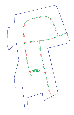
1. Open the CreateSite.dwg file, which you can download from www.sybex.com/go/masteringcivil3d2012. Note that the drawing contains alignments and a boundary parcel, as shown in Figure 5-7.
Figure 5-7: The Create Site drawing contains alignments and soil boundary parcels.
2. Locate the Sites collection on the Prospector tab of Toolspace.
3. Right-click the Sites collection, and select New to open the Site Properties dialog.
4. On the Information tab of the Site Properties dialog, enter Subdivision Lots for the name of your site.
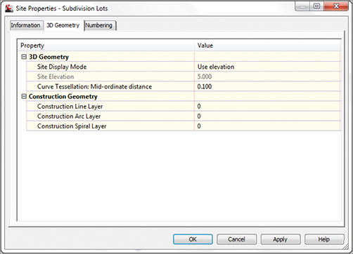
5. Confirm that the settings on the 3D Geometry tab match what is shown on Figure 5-8.
Figure 5-8: Confirm the settings on the 3D Geometry tab.
6. Confirm that the settings on the Numbering tab match Figure 5-9. Everything should be set to 1. Click OK.
Figure 5-9: Confirm the settings on the Numbering tab.

7. Locate the Sites collection on the Prospector tab of Toolspace, and note that your Subdivision Lots site appears on the list.
You can repeat the process for all the sites you anticipate needing over the course of the project.