
Description Keys: Field to Civil 3D
Description keys bridge the gap between the field and the office. The Description Key Set is a listing of field descriptions and how they should look and behave once they are imported into Civil 3D.
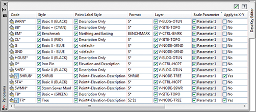
For example, a surveyor may code in BM to indicate a benchmark. When the file is imported into Civil 3D either through the Survey database (as we examined in Chapter 2) or by import from a text file (as you did earlier in this chapter), it will be checked against the description key set. If BM exists in the list as it is in Figure 3-30, then styles, format, layer, and several other parameters are set.
Figure 3-30: Description key set
An interesting fact to note about description keys is that they take over styles and layers set elsewhere. For example, if your point placement options have a layer set but you place a point that matches a description key with a layer set to something different, the description key set “wins.” In the point group creation examples, we set the Overrides tab to have Style and Point Label Style selected (Figure 3-22). Those settings wrestle control of the styles away from the description key and into the hands of the point group.
Code The raw description or field code entered by the person collecting or creating the points. The code works as an identifier for matching the point with the correct description key. Click inside this field to activate it, and then type your desired code. Wildcards are useful when more information is added to the shot in addition to the field code.
Point Style The point style that will be applied to points that meet the code criteria. Check the box, and then click inside the field to activate a style-selection dialog. By default, styles set here will take precedence over styles set elsewhere. For more information on creating or modifying point styles, see Chapter 19.
Point Label Style The point label style that will be applied to points that meet the code criteria. Check the box, and then click inside the field to activate a style-selection dialog. By default, styles set here will take precedence over styles set elsewhere. For more information on creating or modifying point styles, see Chapter 19.
Format The Format column can convert a surveyor’s shorthand into something that is more drafter-friendly. In Civil 3D terms, the Format column converts the raw description to the full description. The default of $* means the raw description and full description will have the same value. In Figure 3-30, Format will convert all codes starting with BM to a full description of BENCHMARK.
If a survey crew is consistent in coding, even fancier formats can be used. The code should always come first, but the crew can use a space to indicate a parameter.
Consider the example raw description: TREE 30 PINE. TREE is the code, or $0. Parameter 1 is 30, or $1 in the Format field. PINE is the second bit of information after the code referred to as parameter 2, or $2. Based on the example description key set in Figure 3-30, this would translate to a full description of PINE 30. You can have up to nine parameters after the code if your survey crew is feeling verbose.
Layer The layer that will be applied to points that meet the code criteria. Click inside this field to activate a layer-selection dialog. The layer set here will take precedence over layer defaults set in the point command settings or the point creation tools.
Scale Parameter The Scale parameter is used to tell Civil 3D which bit of information after the code will be used to scale the symbol. By default it is checked on, but it won’t do anything unless Apply To X-Y is also selected. Once you enable Apply To X-Y, you can change which parameter contains scale information.
In our example, TREE 30 PINE, 30 is the Scale parameter.
Fixed Scale Factor Fixed Scale Factor is an additional scale multiplier that can be applied to the symbol size. The most frequent use of Fixed Scale Factor is to convert a field measurement of inches to feet. If the 30 in our example represents a canopy measurement and is meant to be feet, no fixed scale factor is needed. However, if the 30 represents inches (i.e., a trunk diameter), we would need to turn on Fixed Scale Factor and set the value to 0.0833.
Use Drawing Scale In most cases, you will leave this option unchecked. By default, marker styles dictate that they will grow or shrink based on the annotative scale of the drawing. Generally, this setting is not needed unless you want to scale your point symbol based on a parameter in addition to the scale factor.
Apply To X-Y If you wish to scale symbols based on information in the field code, you need to turn this option on by placing a check mark in the box. This option works with the marker style and the Scale parameter to increase the size of an item to a scale indicated by the surveyor in the raw description.
Apply To Z In most cases, you will leave this option unchecked. Most marker symbols are 2D blocks, so checking this on will have no effect on the point. If your marker symbol consists of a 3D block, it will be stretched by the parameter value, which is rarely needed.
Rotation Parameter, Fixed Rotation, and Rotation Direction These options work similarly to the scale factor parameter except they dictate the rotation of a symbol. They are not widely used, however, since it is often more time-effective to have the drafter rotate the points in CAD than to have the surveyor key in a rotation.
Creating a Description Key Set
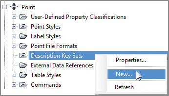
Description key sets appear on the Settings tab of Toolspace under the Point branch. You can create a new description key set by right-clicking the Description Key Sets collection and choosing New, as shown in Figure 3-31.
Figure 3-31: Creating a new description key set on the Settings tab of Toolspace
In the resulting Description Key Set dialog, give your description key set a meaningful name, and click OK. You’ll create the actual description keys in another dialog.
Creating Description Keys
To enter the individual description key codes and parameters, right-click your description key set, as illustrated in Figure 3-32, and select Edit Keys. The DescKey Editor in Panorama appears.
Figure 3-32: Editing a description key set

To enter new codes, right-click a row with an existing key in the DescKey Editor, and choose New or Copy from the context menu, as shown in Figure 3-33.
Figure 3-33: Creating or copying a description key

Using Wildcards
The asterisk (*) acts as a wildcard in many places in Civil 3D. Two of the most common places to use a wildcard are the DescKey Editor and the Point Group Properties dialog. Whereas a DescKey code of TREE flags any points created with that raw description, a DescKey code of TREE* also picks up raw descriptions of TREE1, TREE2, TREEMAPLE, TREEOAK, and so on. You can use the wildcard the same way in the Point Group Properties dialog when specifying items to include or exclude.
Point Groups or Description Keys?
After reading the last two sections, you’re probably wondering which method is better for controlling the look of your points. This question has no absolute answer, but there are some things to take into consideration when making your decision.
Point groups are useful for both visibility control and sorting. They’re dynamic and can be used to control the visibility of points that already exist in your drawing.
Both can be standardized and stored in your Civil 3D template.
Your best bet is probably a combination of the two methods. For large batches of imported points or points that require advanced rotation and scaling parameters, description keys are the better tool. For preparing points for surface building, exporting, and changing the visibility of points already in your drawing, point groups will prove most useful.
Activating a Description Key Set
Once you’ve created a description key set, you should verify the settings for your commands so that Civil 3D knows to match your newly created points with the appropriate key.
The Commands CreatePoints branches are stored on the Settings tab of Toolspace under the Point branch. Edit these command settings by right-clicking, as shown in Figure 3-34.
Figure 3-34: Right-click CreatePoints and choose Edit Command Settings.

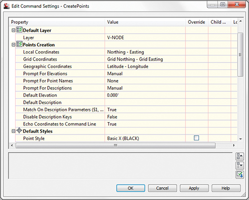
In the Edit Command Settings dialog, ensure that Match On Description Parameters is set to True and that Disable Description Keys is set to False, as shown in Figure 3-35.
Figure 3-35: Do these settings look familiar? Verify that Disable Description Keys is set to False.
It is not uncommon to have multiple description key sets in your template for multiple clients or external survey firms that you work with. If you have multiple description key sets, they are all active, but if a set has a duplicate key, the first one Civil 3D runs across will take precedence. For example, if one set uses FL for flowline but a second set uses FL for fence line, the second occurrence of the FL key gets ignored.
You can control the search order from the Settings tab of Toolspace by right-clicking on Description Keys Sets and selecting Properties. Figure 3-36 shows the Description Key Sets Search Order Listing dialog box. Use the arrows on the right side of the dialog box to set the order. The set listed first takes first priority, then the second, and so on. Note that the listing in the Settings tab may not reflect the true listing in the properties.
Figure 3-36: The Description Key Sets Search Order dialog

Working with Layers and Description Keys Together
It’s common for surveyors to import points, apply description keys, and use the LAYISO command to isolate a group of points and create two-dimensional linework or breaklines. The following exercise walks you through the steps to apply this concept effectively:
1. Open the Description Keys and Layers.dwg file, which you can download from this book’s webpage.
2. Choose Points From File from the Import panel of the Insert tab. The Import Points dialog appears.
3. Be sure the Format is PNEZD (space-delimited), and then click the white plus sign and select Survey.txt (which you can download from this book’s webpage).
4. Select Open and then click OK to exit the dialogs and review the results.
5. In Prospector, the groups will need to be updated. Right-click on Point Groups Category to update all of them at once. Click the Top Of Bank group to highlight it.
6. At the bottom of Toolspace you will see the listing of points. Locate point 3002 in the listing (it should be the first one).
7. Right-click on 3002 and select Zoom To. Point3002 is a Top Of Bank shot, which we will use with the Layer Isolate tool.
8. From the Home tab, on the Layers panel click Layer Isolate. Select one of the points labeled Top Of Bank and press ↵. Notice that the layer is isolated. (Note: Use the REGEN command if you are still seeing other points not on the Top Of Bank layer.)
9. Open the Description Key Sets branch of the Points category on the Settings tab of Toolspace.
10. Right-click on Mastering Civil 3D 2012 and select Edit Keys. The DescKey Editor will open in Panorama.
11. Review the Layer settings for both the BOTB* and TOPB* codes as selected in the DescKey Editor.