Styles and settings should come from your template. Ideally, that template will have all the styles you need for the type of project you are working on. If you find you are constantly changing style settings, examine your workflow. Make sure to start new projects with a proper template. Use the new Import command located on the Manage tab to pull your preferred styles into drawings that you receive from outside sources.
There are hundreds of styles and settings in Civil 3D. The good news is that once you learn to create one or two styles, the rest should get easier. Autodesk has gone to great lengths to make the interface consistent between styles.
When you start a project with the correct template (DWT file), the repetitive task of defining the basic framework for your drawing is already completed. As you know, a DWT file contains the following:
- Units (architectural vs. decimal)
- Layers and respective linetypes
- Text styles
- Dimension and multileader styles
- Layouts and plot setups
- Block definitions
Civil 3D takes the base AutoCAD template and kicks it up several notches. In addition to the items just listed, a Civil 3D template contains the following:
- More specific unit information (international feet, survey feet, or meters)
- Civil object layers
- Ambient settings
- Label styles and formulas (expressions)
- Object styles
- Command settings
- Object naming templates
- Report settings
- Description key sets
Throughout this book, when you started a file from scratch, you used one of the templates that come with Civil 3D when you install it. There is good reason for this; the templates that come with Civil 3D may not be exactly what you want initially, but they are a great starting point when you are customizing your projects.
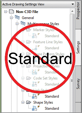
You must always start new projects with a proper Civil 3D template. If you receive a drawing from a non–Civil 3D user, and need to continue it in Civil 3D, you must import the styles and settings. Without suitable styles and settings, all of your object and label styles will show up with the name Standard, as shown in Figure 19-1. You do not want objects and labels to use the Standard style, as it is the Civil 3D equivalent of drawing on layer 0. Items that use the Standard style appear on layer 0 and will contain the most basic display settings.
Figure 19-1: A non–Civil 3D DWG will list all styles as Standard—which is a bad thing.
Importing Styles
Say someone sends you a drawing that was not done in Civil 3D. Perhaps it was exported from MicroStation, or initially created in Land Desktop, Carlson, or Eagle Point. You now have the task of creating Civil 3D objects, but making this task even more difficult is that there are no Civil 3D styles present. Perhaps the drawing was created in Civil 3D, but your organization’s styles look completely different.
Luckily, importing styles from an existing drawing or template has gotten much easier in Civil 3D 2012. You can find the new Import Styles button on the Styles panel of the Manage tab. When you click the button, you will be prompted to browse for the template (DWT) or drawing (DWG) that contains the styles you are looking for.
Once you select the file whose styles you will import, the dialog shown in Figure 19-2 appears.
Figure 19-2: Import Civil 3D Styles dialog
Notice the Import Settings option at the bottom of the dialog. This option is turned on by default. As you look through the list of styles to be imported, you will notice that some items are grayed out and can’t be modified.
The grayed-out styles represent items in command settings. Styles referred to in command settings must be imported if the Import settings option is turned on. You will read about command settings in the upcoming section.
You will also notice items with a warning symbol such as Basic in Figure 19-2. The warning symbol indicates there is a style in the current drawing with the same name as a style in the batch to be imported. Use the Uncheck Conflicting button if you do not want styles in the destination drawing to be overwritten. If you leave these items checked on, the incoming styles “win.” If you are not sure if there is a difference between the styles, pause your cursor over the style name and a tooltip will tell you what (if any) difference exists.
Use the Uncheck Added button if you only want styles with the same name to come in. Wherever possible, Civil 3D will release items in the To Be Added categories. In cases where a style is used by a setting, you will not be able to uncheck it unless you do not import settings.
A style in the current drawing will be deleted if the source drawing does not contain a style with the same name. Use the Uncheck deleted to prevent the style from being deleted.
Drawing Settings
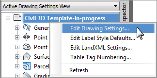
The first stop when setting up a Civil 3D template is the Drawing Settings area. Access the Edit Drawing Settings command by selecting the Settings tab in Toolspace and right-clicking on the name of the drawing, as shown in Figure 19-3.
Figure 19-3: Accessing the drawing settings
Each tab in the Drawing Settings dialog controls a different aspect of the drawing. Most of the time, you’ll pick up information for the Object Layers, Abbreviations, and Ambient Settings tabs from a companywide template. The drawing scale and coordinate information change for every job, so you’ll visit the Units And Zone and Transformation tabs frequently.
Settings for Units And Zone, Object Layers, and Abbreviations are specified in this area and nowhere else. The Ambient Settings are set drawing-wide at this level but can be overridden “downstream” for object-specific control.
Units And Zone Tab
The Units And Zone tab (Figure 19-4) lets you specify metric or imperial units for your drawing. You can also specify the conversion factor between systems. If you choose a coordinate system with International or US Foot specified, this setting will become unavailable.
Figure 19-4: Units And Zone tab
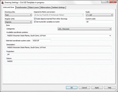
This tab also includes the options Scale Objects Inserted From Other Drawings and Set AutoCAD Variables To Match. The Set AutoCAD Variables To Match option sets the base AutoCAD angular units, linear units, block insertion units, hatch pattern, and linetype units to match the values placed in this dialog. As shown in Figure 19-4, you do want these checked on.
The scale that you see on the right side of the Units And Zone tab is the same as your annotation scale. You can change it here, but it is much easier to select your annotation scale from the bottom of the drawing window.
If you choose to work in assumed coordinates, you can leave the Zone set to No Datum, No Projection. To set the coordinate system for your locale, first set the category from the long list of possibilities. Civil 3D is a worldwide product; therefore, most recognized surveying coordinate systems (including obsolete ones) can be found in the options. Once your coordinate system has been established, you can change it on the Transformation tab if desired.
Try the following quick exercise to practice:
1. Open the drawing Civil 3D Template-in-progress.dwg file, which you can download from www.sybex.com/go/masteringcivil3d2012.
2. From the Settings tab of Toolspace, right-click on the name of the drawing and select Edit Drawing Settings. Switch to the Units And Zone tab.
3. Select USA, Wisconsin from the Categories drop-down menu.
4. Select NAD83 Wisconsin State Planes, South Zone, US Foot from the Available Coordinate Systems drop-down menu.
5. Save the drawing for the next exercise.
Transformation Tab
Earth is neither flat nor a perfect sphere. In reality, Earth is more of a squashed sphere, wider at the equator than at the poles. The mathematical approximation of the Earth’s physical shape is called an ellipsoid. The ellipsoid is constantly being fine-tuned to increase accuracy for precise geographic modeling. To make matters even more complicated, the gravitational pull of Earth is not distributed evenly, creating a slight skew between what a surveyor measures and how it relates to the ellipsoid. The gravitational representation of Earth is referred to as the geoid.
Luckily, most engineers and surveyors do not need to worry about all this. Most survey-grade GPS equipment takes care of the transformation to local grid coordinates for you. In the United States, state plane coordinate systems already have regional projections taken into account. In the rare case that surveyors need to transform local observations from geoid to ellipsoid and ellipsoid to grid manually, the Transformation tab makes the computation quickly.
With a base coordinate system selected, you can do any further refinement you’d like using the Transformation tab. The coordinate systems on the Units And Zone tab can be refined to meet local ordinances, tie in with historical data, complete a grid to ground transformation, or account for minor changes in coordinate system methodology. These changes can include the following:
Apply Sea Level Scale Factor This value is known in some circles as elevation factor or orthometric height scale. Sea Level Factor takes into account the mean elevation of the site and the spheroid radius that is currently being applied as a function of the selected zone ellipsoid.
Grid Scale Factor At any given point on a projected map, there is a distortion between the “flat” measurement and the measurement on the ellipsoid. Grid Scale Factor is based on a 1:1 value, a user-defined uniform scale factor, a reference point scaling, or a prismoidal transformation in which every point in the grid is adjusted by a unique amount.
Reference Point To apply Grid Scale Factor and Sea Level Factor correctly, you need to tell Civil 3D where you are on Earth. Reference Point can be used to set a singular point in the drawing field via pick or via point number, local northing and easting, or grid northing and easting values.
Rotation Point Rotation Point can be used to set the reference point for rotation via the same methods as the Reference Point.
Specify Grid Rotation Angle Some people may know this as the Convergence angle. This is the angle between Grid North and True North. Enter an amount or set a line to north by picking an angle or deflection in the drawing. You can use this same method to set the azimuth if desired.
Most engineering firms work on either a defined coordinate system or an arbitrary system, so none of these changes are necessary. Given that, this tab will be your only method of achieving the necessary transformation for certain surveying and geographic information system (GIS)–based and Land Surveying–based tasks. It should be noted that this is not the place to transform assumed coordinates to a predefined coordinate system. See Chapter 2, “Survey,” to learn how to translate a survey.
Object Layers Tab
Civil 3D and AutoCAD layers have a love–hate relationship with each other. Civil 3D is built on top of AutoCAD; therefore, all the objects do reside on layers. However, Civil 3D is not traditional CAD. Your surfaces, corridors, points, profiles, and everything else generated by Civil 3D are dynamic objects rather than simple lines, arcs, or circles.
When you created an alignment in Chapter 6, “Alignments,” for example, you did not have to think about the current layer. You also were not concerned with which layer the polyline was on when you converted it to an alignment. This is because Civil 3D styles “push” objects and labels to the correct layer as part of their intelligence.
Layers are found in several areas of the Civil 3D template. The first location you will examine is the layers found in the Drawing Settings area. The layers listed here represent overall layers. For those of you who are familiar with AutoCAD blocks, it is useful to think of these layers in the same way as a block’s insertion layer.
In the Object Layers tab, every Civil 3D object must have a layer set, as shown in Figure 19-5. Do not leave any object layers set to 0. An optional modifier can be added to the beginning (prefix) or end (suffix) of the layer name to further separate items of the same type.
Figure 19-5: Every object is on a layer; the corridor layer contains a modifier.
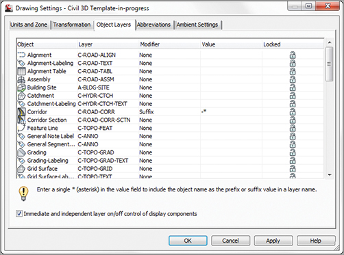
A common practice is to add wildcard suffixes to corridor, surface, pipe, and structure layers to make it easier to manipulate them separately. For example, if the layer for a corridor is specified to be C-ROAD-CORR and a suffix of -* (dash asterisk, as shown in Figure 19-5) is added as the modifier value, a new layer will automatically be created when a new corridor is created. The resulting layer will take on the name of the corridor. If the corridor is called 13th Street, the new layer name will be C-ROAD-CORR-13th Street. This new layer is created once, and is not dynamic to the object name. In other words, if you decide to rename “13th Street” to “Stephen Colbert Street,” the layer remains C-ROAD-CORR-13th Street.
If the main layer name you are after does not exist in the drawing, you can create it as you work through the Object Layers dialog. Click the New button, as shown in Figure 19-6, and set up the layer as needed.
Figure 19-6: Click New to add a new layer.

In the following exercise, you set object layers in a template:
1. Open the drawing Civil 3D Template-in-progress.dwg file, which you can download from this book’s web page.
2. From the Settings tab of Toolspace, right-click on the name of the drawing and select Edit Drawing Settings. Switch to the Object Layers tab.
3. Click in the Layer field next to Alignment. Create a new layer called C-ROAD-ALIGN. Set the new layer as the layer for the Alignment object.
4. Set the layer for Building Site to A-BLDG-SITE.
5. Set the layer for Catchment-Labeling to C-HYDR-CTCH-TEXT.
6. For the corridor layer, keep the main layer as C-ROAD-CORR. Set the Modifier to Suffix. Set the modifier value to -*. The asterisk acts as a wildcard that will add the corridor name as part of a unique layer for each corridor.
7. Scroll down to the pipe and structure listing. In this area you will create several new layers and add suffix information:
- For Pipe, create a layer called C-NTWK-PIPE with a suffix of -*.
- For Pipe-Labeling, create a new layer called C-NTWK-PIPE-TEXT.
- For Pipe And Structure Table, set the layer to C-NTWK-PIPE-TEXT.
- For Pipe Network Section, create a new layer called C-NTWK-XSEC.
- For Pipe Network Profile, create a new layer called C-NTWK-PROF.
- Scroll down a bit further and create a new layer for Structure called C-NTWK-STRC. Add a suffix of -*.
- For Structure-Labeling, create a new layer called C-NTWK-STRC-TEXT.
- Add a suffix to the Tin Surface object layer of -*.
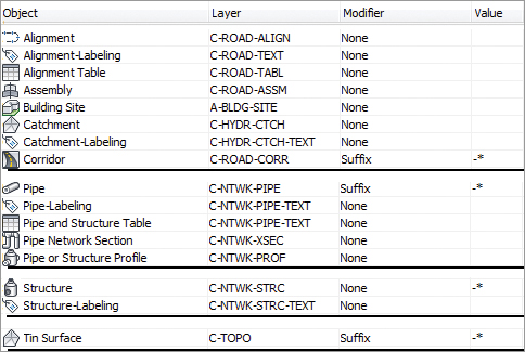
Your layers and suffixes should now resemble Figure 19-7.
Figure 19-7: Examples of the completed layer names in the Object Layers tab
8. Place a check mark next to Immediate And Independent Layer On/Off Control Of Display Components. This setting will allow you to use the On/Off toggle in Layer Manager to work with Civil 3D objects.
9. Click Apply and then OK. Save the drawing for use in the next exercise.
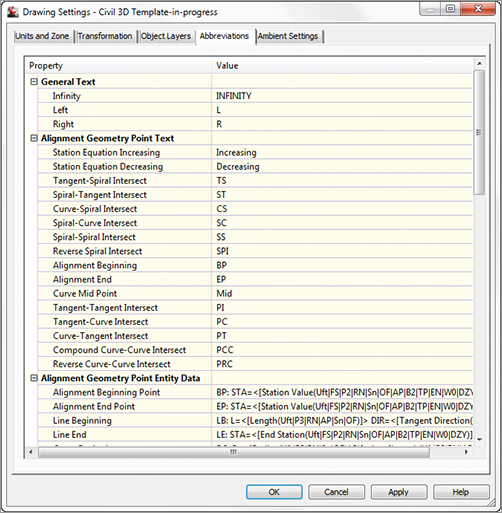
Abbreviations Tab
When you add labels to certain objects, Civil 3D automatically uses the abbreviations from this area to indicate geometry features. For example, left is L and right is R.
It is unusual to need to make many changes in this area, since Civil 3D uses industry-standard abbreviations wherever they are found. Civil 3D is also very customizable if you’d rather use VPI instead of PVI for Point of Vertical Intersection.
In most cases, changing an abbreviation is as simple as clicking in the Value field and typing a new one. Notice that the Alignment Geometry Point Entity Data section has a larger set of values and some special coding attached (as shown toward the bottom of Figure 19-8). These are more representative of other label styles. You will visit the Text Component Editor a little later in this chapter in the section “Label Styles.”
Figure 19-8: Customizable down to the letter, the Abbreviations tab
Ambient Settings Tab
Examine the settings in the Ambient Settings tab to see what can be set here. The main options you’ll want to adjust are in the General category and the display precision in the subsequent categories.
The precision that you see in this dialog does not change the label precision. The precision you see here is the number of decimal places reported to you in various dialogs.
Being familiar with the way this tab works will help you further down the line, because almost every other settings dialog in the program works like the one shown in Figure 19-9.
Figure 19-9: Ambient settings at the main drawing level
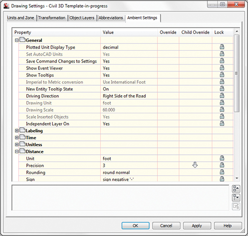
Plotted Unit Display Type Civil 3D knows you want to plot at the end of the day. In this case, it’s asking how you would like your plotted units measured. For example, would you like that bit of text to be 0.25″ tall or ¼″ high? Most engineers are comfortable with the Leroy method of text heights (L80, L100, L140, and so on), so the decimal option is the default.
Set AutoCAD Units This displays whether or not Civil 3D should attempt to match AutoCAD drawing units, as specified on the Units And Zone tab.
Save Command Changes To Settings Set this to Yes. This setting is incredibly powerful but a secret to almost everyone. By setting it to Yes, you ensure that your changes to commands will be remembered from use to use. This means if you make changes to a command during use, the next time you call that Civil 3D command, you won’t have to make the same changes. It’s frustrating to do work over because you forgot to change one of the five things that needed changing, so this setting is invaluable.
Show Event Viewer Event Viewer is Civil 3D’s main feedback mechanism, especially when things go wrong. It can get annoying, however, and it takes up valuable screen real estate (especially if you’re stuck with one monitor!), so many people turn it off. We recommend leaving it on and pushing it to the side until needed.
Show Tooltips One of the cool features that people remark on when they first use Civil 3D is the small pop-up that displays relevant design information when the cursor is paused on the screen. This includes things such as station-offset information, surface elevation, section information, and so on. Once a drawing contains numerous bits of information, this display can be overwhelming; therefore, Civil 3D offers the option to turn off these tooltips universally with this setting. A better approach is to control the tooltips at the object type by editing the individual feature settings. You can also control the tooltips by pulling up the properties for any individual object and looking at the Information tab.
Imperial To Metric Conversion This setting displays the conversion method specified on the Units And Zone tab. The two options currently available are US Survey Foot and International Foot.
New Entity Tooltip State You can also control tooltips on an individual object level. For instance, you might want tooltip feedback on your proposed surface but not on the existing surface. This setting controls whether the tooltip is turned on at the object level for new Civil 3D objects.
Driving Direction Specifies the side of the road that forward-moving vehicles use for travel. This setting is important in terms of curb returns and intersection design.
Drawing Unit, Drawing Scale, and Scale Inserted Objects These settings were specified on the Units And Zone tab but are displayed here for reference and so that you can lock them if desired.
Independent Layer On This is the same control that was set on the Object Layers tab. Yes is the recommended setting.
The Ambient Settings for Direction offer the following choices:
- Unit: Degree, Radian, and Grad
- Precision: 0 through 8 decimal places
- Rounding: Round Normal, Round Up, and Truncate
- Format: Decimal, two types of DDMMSS, and Decimal DMS
- Direction: Short Name (spaced or unspaced) and Long Name (spaced or unspaced)
- Capitalization
- Sign
- Measurement Type: Bearings, North Azimuth, and South Azimuth
- Bearing Quadrant
When you’re using the Bearing Distance transparent command, for example, these settings control how you input your quadrant, your bearing, and the number of decimal places in your distance.
Explore the other categories, such as Angle, Lat Long, and Coordinate, and customize the settings to how you work.
At the bottom of the Ambient Settings tab is a Transparent Commands category. These settings control how (or if) you’re prompted for the following information:
Prompt For 3D Points Controls whether you’re asked to provide a z elevation after x and y have been located.
Prompt For Y Before X For transparent commands that require x and y values, this setting controls whether you’re prompted for the y-coordinate before the x-coordinate. Most users prefer this value set to False so they’re prompted for an x-coordinate and then a y-coordinate.
Prompt For Easting Then Northing For transparent commands that require Northing and Easting values, this setting controls whether you’re prompted for the Easting first and the Northing second. Most users prefer this value set to False, so they’re prompted for Northing first and then Easting.
Prompt for Longitude Then Latitude For transparent commands that require longitude and latitude values, this setting controls whether you’re prompted for Longitude first and Latitude second. Most users prefer this set to False, so they’re prompted for Latitude and then Longitude.
Drawing Precision vs. Label Precision
The precision and units that you are seeing in the Ambient settings and commands settings only affect how the values are reported to you in dialogs. These settings are not related to the number of decimal places or units displayed in labels.
You will work with labels later in this chapter in the section “Label Styles.”
The settings that are applied here can also be changed at the object levels. For example, you may typically want elevation to be shown to two decimal places, but when looking at surface elevations, you might want just one. The Override and Child Override columns give you feedback about these types of changes. See Figure 19-10.
Figure 19-10: The Child Override indicator in the Time, Distance, and Elevation values

The Override column shows whether the current setting is overriding something higher up. Because you’re at the Drawing Settings level, these are clear. However, the Child Override column displays a down arrow, indicating that one of the objects in the drawing has overridden this setting. After a little investigation of the objects, you’ll find the override is in the Edit Feature Settings of the Profile View, as shown in Figure 19-11.
Figure 19-11: The Profile Elevation Settings and the Override indicator
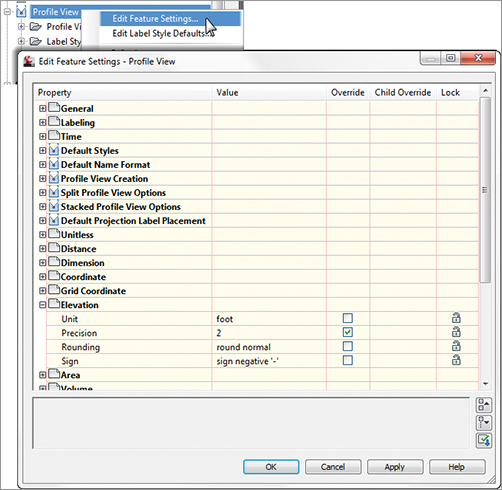
Notice that in this dialog, the box is checked in the Override column. This indicates that you’re overriding the settings mentioned earlier, and it’s a good alert that things have changed from the general Drawing Settings to this Object Level setting.
But what if you don’t want to allow those changes? Each Settings dialog includes one more column: Lock. At any level, you can lock a setting, graying it out for lower levels. This can be handy for keeping users from changing settings at the lower level that perhaps should be changed at a drawing level, such as sign or rounding methods.
Object Settings
If you click the Expand button next to the drawing name, you see the full array of objects that Civil 3D uses to build its design model. Each of these has special features unique to the object being described, but there are some common features as well. Additionally, the General collection contains settings and styles that are applied to various objects across the entire product.
The General collection serves as the catchall for styles that apply to multiple objects and for settings that apply to no objects. For instance, the Civil 3D General Note object doesn’t really belong with the Surface or Pipe collections. It can be used to relate information about those objects, but because it can also relate to something like “Don’t Dig Here!” it falls into the General category. The General collection has three components (or branches):
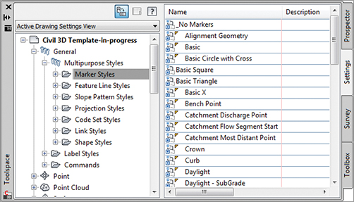
Multipurpose Styles These styles are used in many objects to control the display of component objects. The Marker Styles and Link Styles collections are typically used in cross-section views, whereas the Feature Line Styles collection is used in grading and other commands. Figure 19-12 shows the full collection of multipurpose styles and some of the marker styles that ship with the product.
Figure 19-12: General multipurpose styles and some marker styles
Toolspace is shown horizontally in Figure 19-13 and Figure 19-14 for illustration purposes. If you like the way this looks, you can also set your Toolspace like this by clicking the orientation toggle at the top. This will bring the preview area to the right of Toolspace.
Figure 19-13: Line label styles
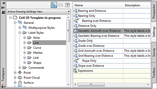
Label Styles The Label Styles collection allows Civil 3D users to place general text notes or label single entities while still taking advantage of Civil 3D’s flexibility and scaling properties. With the various label styles shown in Figure 19-13, you can get some idea of their use.
Label styles are a critical part of producing plans with Civil 3D. In the section “Label Styles” later in this chapter, you’ll learn how to build a new basic label and explore some of the common components that appear in every label style throughout the product.
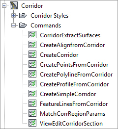
Commands Almost every branch in the Settings tree contains a Commands folder. Expanding this folder, as shown in Figure 19-14, shows the typical long, unspaced command names that refer to the parent object.
Figure 19-14: Corridor command settings in Toolspace