
You can edit pipe networks in several ways:
- Using drawing layout edits such as grip, move, and rotate
- Grip-editing the pipe size
- Using vertical-movement edits using grips in profile (see the “Vertical Movement Edits Using Grips in Profile” section later in this chapter)
- Using tabular edits in the Pipe Networks branch in Prospector
- Right-clicking a network part to access tools such as Swap Part or Pipe/Structure Properties
- Returning to the Network Layout Tools toolbar by right-clicking the object and choosing Edit Network
- Selecting a network part to access the Pipe Networks contextual tab on the Ribbon
With the exception of the last option, each of these methods is explored in the following sections.
Editing Your Network in Plan View
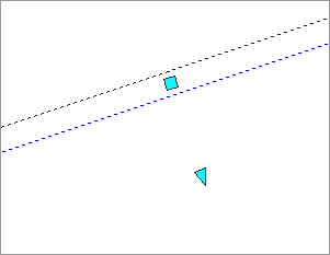
When selected, a structure has two types of grips, shown in Figure 13-40. The first is a square grip located at the structure insertion point. You can use this grip to grab the structure and stretch/move it to a new location using the insertion point as a base point. Stretching a structure results in the movement of the structure as well as any connected pipes. You can also scroll through Stretch, Move, and Rotate by using your spacebar once you’ve grabbed the structure by this grip.
Figure 13-40: Two types of structure grips
The second structure grip is a rotational grip that you can use to spin the structure about its insertion point. This is most useful for aligning eccentric structures, such as rectangular junction structures.
Also note that common AutoCAD Modify commands work with structures. You can execute the following commands normally (such as from a toolbar or keyboard macro): Move, Copy, Rotate, Align, and Mirror (Figure 13-41a). (Scale doesn’t have an effect on structures.) Keep in mind that the Modify commands are applied to the structure model itself; depending on how you have your style established, it may not be clear that you’ve made a change. For example, if you execute the Mirror command, you can select the structures to see the results or use a 3D visual style, such as in Object Viewer, to see the modeled parts, as shown in Figure 13-41b.
Figure 13-41: Mirrored structures seen (a) in plan view by their style and (b) in 3D wireframe visual style using Object Viewer
You can use the AutoCAD Erase command to erase network parts. Note that erasing a network part in plan completely removes that part from the network. Once erased, the part disappears from plan, profile view, Prospector, and so on.
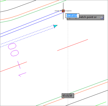
When selected, a pipe end has two types of grips (see Figure 13-42). The first is a square Endpoint-Location grip. Using this grip, you can change the location of the pipe end without constraint. You can move it in any direction; make it longer or shorter; and take advantage of Stretch, Move, Rotate, and Scale by using your spacebar.
Figure 13-42: Two types of Pipe-End grips
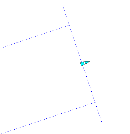
The second grip is a Pipe-Length grip. This grip lets you extend a pipe along its current bearing.
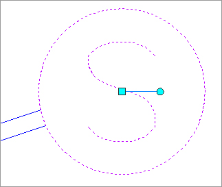
A pipe midpoint also has two types of grips (see Figure 13-43). The first is a square Location grip that lets you move the pipe using its midpoint as a base point. As before, you can take advantage of Stretch, Move, Rotate, and Scale by using your spacebar.
Figure 13-43: Two types of pipe Midpoint grips
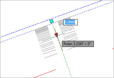
The second grip is a triangular-shaped Pipe-Diameter grip. Stretching this grip gives you a tooltip showing allowable diameters for that pipe, which are based on your parts list. Use this grip to make quick, visual changes to the pipe diameter.
Also note that common AutoCAD Modify commands work with pipes. You can execute the following commands normally (such as from a toolbar or keyboard macro): Move, Copy, Rotate, Align, Scale, and Mirror. Remember that executing one of these commands often results in the modified pipe becoming disconnected from its structures. After the completion of a Modify command, be sure to right-click your pipe and choose Connect To Part to remedy any disconnects.
You can use the AutoCAD Erase command to erase network parts. Note that erasing a network part in plan completely removes that part from the network. Once erased, the part disappears from plan view, profile view, Prospector, and so on.
Dynamic Input and Pipe Network Editing
Dynamic Input (DYN) has been in AutoCAD-based products since the 2006 release, but many Civil 3D users aren’t familiar with it. For some of the more command line–intensive Civil 3D tasks, DYN isn’t always useful, but for pipe network edits, it provides a visual way to interactively edit your pipes and structures.
To turn DYN on or off at any time, click DYN at the bottom of your Civil 3D window.
Structure Rotation While DYN is active, you get a tooltip that tracks rotation angle.

Press your down arrow key to get a pop-up menu that allows you to specify a base point followed by a rotation angle, as well as options for Copy and Undo. DYN combined with the Rotate command is beneficial when you’re rotating eccentric structures for proper alignment.
Pipe Diameter When you’re using the Pipe-Diameter grip edit, DYN gives you a tooltip to assist you in choosing your desired diameter. Note that the tooltip depends on your drawing units.
Pipe Length This is probably the most common reason to use DYN for pipe edits. Choosing the Pipe Length grip when DYN is active shows tooltips for the pipe’s current length and preview length, as well as fields for entering the desired pipe total length and pipe delta length. Use your Tab key to toggle between the Total Length and Delta Length fields. One of the benefits of using DYN in this interface is that even though you can’t visually grip-edit a pipe to be shorter than its original length, you can enter a total length that is shorter than the original length. Note that the length shown and edited in the DYN interface is the 3D center-to-center length.
Pipe Endpoint Edits Similar to pipe length, pipe endpoint location edits can benefit from using DYN. The active fields give you an opportunity to input x- and y-coordinates.
Pipe Vertical Grip Edits in Profile Using DYN in profile view lets you set exact invert, centerline, or top elevations without having to enter the Pipe Properties dialog or Prospector. Choose the appropriate grip, and note that the active DYN field is Tracking Profile Elevation. Enter your desired elevation, and your pipe will move as you specify.

Making Tabular Edits to Your Pipe Network
Another method for editing pipe networks is in a tabular form using the Pipe Networks branch in Prospector (see Figure 13-44).
Figure 13-44: The Pipe Networks branch in Prospector
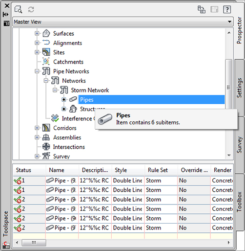
To edit pipes in Prospector, highlight the Pipes entry under the appropriate pipe network. For example, if you want to edit your sanitary sewer pipes, expand the Sanitary Sewers branch and select the Pipes entry. You should get a preview pane that lists the names of your pipes and some additional information in a tabular form. The same procedure can be used to list the structures in the network.
White columns can be edited in this interface. Gray columns are considered calculated values and therefore can’t be edited.
You can adjust many things in this interface, but you’ll find it cumbersome for some tasks. The interface is best used for the following:
Batch Changes to Styles, Render Materials, Reference Surfaces, Reference Alignments, Rule Sets, and So On Use your Shift key to select the desired rows, and then right-click the column header of the property you’d like to change. Choose Edit, and then select the new value from the drop-down menu. If you find yourself doing this on every project for most network parts, confirm that you have the correct values set in your parts list and in the Pipe Network Properties dialog.
Batch Changes to Pipe Description Use your Shift key to select the desired rows, and then right-click the Description column header. Choose Edit, and then type in your new description. If you find yourself doing this on every project for most network parts, check your parts list. If a certain part will always have the same description, you can add it to your parts list and prevent the extra step of changing it here.
Changing Pipe or Structure Names You can change the name of a network part by typing in the Name field. If you find yourself doing this on every project for every part, check that you’re taking advantage of the Name templates in your Pipe Network Properties dialog (which can be further enforced in your Pipe Network command settings).
You can Shift-select and copy the table to your Clipboard and insert it into Microsoft Excel for sorting and further study. (This is a static capture of information; your Excel sheet won’t update along with changes to the pipe network.)
This interface can be useful for changing pipe inverts, crowns, and centerline information. It’s not always useful for changing the part rotation, insertion point, start point, or endpoint. It isn’t as useful as many people expect because the pipe inverts don’t react to each other. If Pipe A and Pipe B are connected to the same structure, and Pipe A flows into Pipe B, changing the end invert of Pipe A does not affect the start invert of Pipe B automatically. If you’re used to creating pipe design spreadsheets in Excel using formulas that automatically drop connected pipes to ensure flow, this behavior can be frustrating.
Context Menu Edits
You can perform many edits at the individual part level by using your right-click menu.
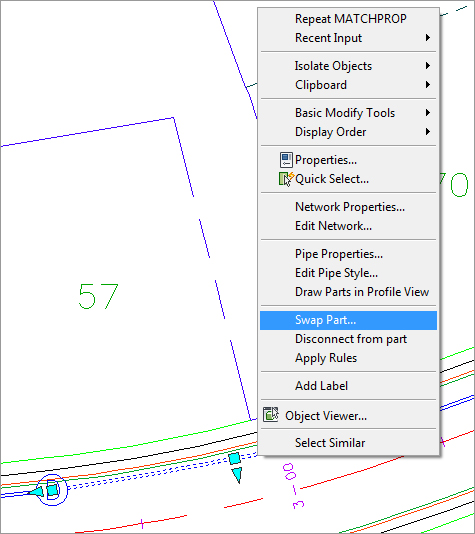
If you realize you placed the wrong part at a certain location—for example, if you placed a catch basin where you need a drainage manhole—use the Swap Part option on the context menu (see Figure 13-45). You’re given a list of all the parts from all the parts lists in your drawing.
Figure 13-45: Right-clicking a network part brings up a context menu with many options, including Swap Part.
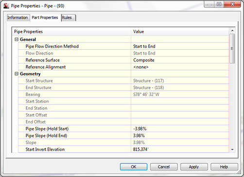
The same properties listed in Prospector can be accessed on an individual part level by right-clicking and choosing Pipe Properties or Structure Properties. A dialog like the Structure Properties dialog in Figure 13-46 opens, with several tabs that you can use to edit that particular part.
Figure 13-46: The Part Properties tab in the Structure Properties dialog gives you the opportunity to perform many edits and adjustments.
Editing with the Network Layout Tools Toolbar
You can also edit your pipe network by retrieving the Network Layout Tools toolbar. This is accomplished by selecting a pipe network object, right-clicking, and choosing Edit Network, or by changing to the Modify tab and clicking Pipe Network on the Design panel.
Once the toolbar is up, you can continue working exactly the way you did when you originally laid out your pipe network.
This exercise will give you hands-on experience in making a variety of edits to a sanitary and storm-drainage pipe network:
1. Open the EditingPipesPlan.dwg file. This drawing includes a sanitary sewer network and a storm drainage network as well as some surfaces and alignments.
2. Select the structure STM STR 2 in the drawing. Right-click and choose Swap Part. Select the 2 × 4 structure from the Rectangular Junction Structure NF. Click OK.
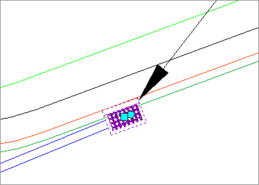
3. Select the newly placed catch basin so that you see the two Structure grips. Use the Rotational grip and your nearest osnap to align the catch basin as shown in Figure 13-47.
Figure 13-47: Rotate and move the catch basin into place along the curb.
4. Use the AutoCAD Erase command to erase Structure-(5).
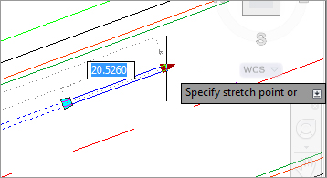
5. Click DYN to turn it on, and select the labeled pipe. Use the triangular Endpoint grip and the DYN tooltip to lengthen it to a total length of 200′ (60.96 m), as shown in Figure 13-48. (Note that this is the 3D Center To Center Pipe Length.)
Figure 13-48: Lengthen the pipe to 200′ (60.96 m).
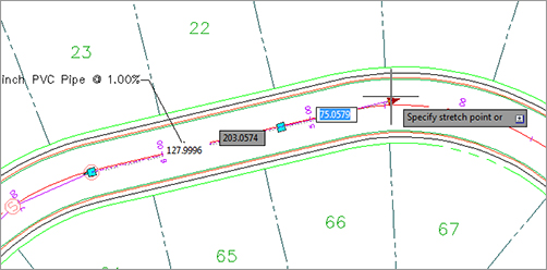
Toggling Numbers
When you grip the triangular Endpoint grip, DYN shows the amount that the pipe is being lengthened. We want to lengthen the entire pipe run. Pressing the Tab key toggles between the additional pipe lengthened versus the entire pipe length.
6. Select any pipe in the network. Right-click and choose Edit Network.
7. Select Draw Structures Only from the drop-down menu in the Draw Pipes And Structures selection box. Place a concentric structure at the end of the lengthened pipe discussed in step 5.
8. Select Structure-(1) in the drawing. Right-click and choose Structure Properties. Switch to the Part Properties tab. Scroll down to the Sump Depth field, and change the value to 0′. Click OK to exit the Structure Properties dialog.
9. Expand the Pipe Networks Networks Sanitary Sewer Network branches in Prospector in Toolspace, and select the Structures entry. Use the tabular interface in the preview pane area of Prospector to change the names of Structures (10) through (13) to MH1 through MH4.
I Thought I Took Care of That Sump?
In step 8, you were instructed to make the sump depth 0. So why isn’t the bottom of the structure even with the pipe then? The answer lies in Part Builder (discussed earlier). Structures are created using the outermost edges, and in the case of structures this includes a 6” (15.24 cm) sump.
You can go into Part Builder to fix this by adding a zero value to the Floor Thickness list:
1. Start Part Builder.
2. Select the Concentric Cylinder part and click Edit.
3. Right-click the FTh value (FTh = Floor Thickness).
4. Highlight the FTh value and select Edit.
5. In the Edit Values dialog, click the Add button.
6. Type 0 for the new value and click OK.
7. Exit Part Builder, saving the part.
8. Back in Prospector, choose Settings Pipe Network Parts Lists Storm Sewer.
9. Expand the part you changed earlier, right-click, and choose Edit.
10. In the Floor Thickness, notice that there is now a Floor Thickness of 0.