Now that you have an understanding of cross sections and you can compute how much cut-fill is required at each cross section, let’s take a look at the “big picture”—that is, Mass Haul.
Mass Haul is basically the art of moving dirt around with the least amount of dirt brought into the site to satisfy grading requirements (borrowed) or excess dirt hauled out of the site (waste).
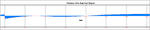
Many contractors like to see a Mass Haul diagram so they can visualize the overall road and what dirt they need to move around. The goal is to achieve zero balance—that is, no cut or fill. Figure 12-27 shows Syrah Way depicted in a Mass Haul diagram.
Figure 12-27: Syrah Way Mass Haul diagram
Taking a Closer Look at the Mass Haul Diagram
Figure 12-27 showed a typical Mass Haul diagram, but what did it all mean? Let’s take a closer look at our example and explore some common terminology used.
The Mass Haul diagram is based on Elevation 0 (zero). When the line appears above the zero elevation point, it is showing Net Cut values. When the line appears below the zero elevation point, it is showing Net Fill values, as you can see in Figure 12-28.
Figure 12-28: The Elevation, Net Cut, and Net Fill on the Mass Haul diagram

As the Mass Haul diagram continues, it shows the cumulative effect of Net Cut and Fill for the alignment. When the Net Cut and Net Fill converge at the zero elevation, the alignment at that point is balanced (Figure 12-29).
Figure 12-29: The Cumulative earthwork for the alignment
Here is some of the nomenclature you might encounter:
Balanced The state where the cumulative cut and fill volumes are equal.
Origin Point The beginning of the Mass Haul diagram, typically at Station 0 + 00, but can vary depending on your stationing.
Borrow A negative value typically at the end of the Mass Haul diagram that indicates Fill material that will need to be brought into the site.
Waste A positive value typically at the end of the Mass Haul diagram that indicates Cut material that will need to be hauled out of the site.
Free Haul Earthwork that has been contractually agreed upon to be moved by a contractor. This typically involves a contracted distance.
Over Haul Earthwork that has is not contractually agreed upon to be moved. This excess can be used for borrow pits or waste piles.
Create a Mass Haul Diagram
Now, let’s put it all together and build a Mass Haul diagram in Civil 3D for Frontenac Drive and you’ll see how easy it is:
1. Open the MassHaul.dwg file. Remember, you can download all the data files from this book’s web page.
2. From the Analyze tab and Volumes And Materials panel, select Mass Haul. The Create Mass Haul Diagram dialog opens.
3. Make changes as shown in Figure 12-30 and click Next.
Figure 12-30: The Create Mass Haul Diagram dialog, General options

4. On the Mass Haul Display Options area (Figure 12-31), explore the options and click Next.
Figure 12-31: The Create Mass Haul Diagram options, Mass Haul Display Options page

5. In the Balancing Options area, make the changes as shown in Figure 12-32 and click Create Diagram.
6. Find a clear spot on your drawing to place the Mass Haul diagram. The diagram should look similar to Figure 12-33.
Figure 12-32: The Create Mass Haul diagram, Balancing Options page

Figure 12-33: The completed Mass Haul diagram
The Create Mass Haul Diagram Dialog Explained
Now that we have created a Mass Haul diagram, let’s look into each of the wizard screens.
The General Area
This screen contains general options for the Mass Haul diagram. Refer to Figure 12-30:
Select Alignment Select the alignment that has been previously sampled. You can select from the drop-down menu, or by using the drawing selector icon to the right of the alignment.
Sample Line Group This is the predefined sample group that you wish to use for the Mass Haul diagram. Remember that an alignment can have multiple sample line groups. You can select the sample line group by using the drop-down menu or by using the drawing selector icon to the right of the sample line group.
Mass Haul View Name You can name the Mass Haul diagram by typing in a name, or by leaving it at the default. The name will appear as MHV – 1 (or whatever the next logical number is).
Description Enter a verbose description of the Mass Haul diagram here.
Mass Haul View Style You can set predefined looks of Mass Haul diagrams or create your own. For more on styles, refer to Chapter 19, “Styles.”
Mass Haul View Layer You can set a specific layer for the Mass Haul diagram.
Mass Haul Display Options
This section shows more options for visual display. Refer to Figure 12-31:
Material List This is the material list that was predefined when you used the Compute Materials dialog.
Choose a Material to Display as the Mass Haul Line. You can choose Total Volume, Total Cut Volume, Total Fill Volume, Total Unusable Volume, Ground Removed, and Ground Fill.
Mass Haul Line Name You can give a unique name for the Mass haul line:
Description Enter a verbose description for the Mass haul line.
Mass Haul Line Style You can set predefined looks of Mass Haul lines or create your own.
Mass Haul Line Layer You can set a specific layer for the Mass Haul line.
Balancing Options
In this section, you set options such as free haul options and adding borrow pits and/or dump sites. Refer to Figure 12-32.
Free Haul Options By checking this box, you set the agreed-upon maximum distance that earth will be hauled. When you check the box, you enter a distance in the box beneath it.
Add/Remove Borrow Pits and Dump Sites You can enter (by station and cubic yard) the area(s) you wish to place a borrow pit and/or dump site.
Editing a Mass Haul Diagram
When you create a Mass Haul diagram, you can easily modify parameters and get instant feedback on your diagram. Follow these steps to see how:
1. Continuing in the MassHaul.dwg, click on the Mass Haul Object (not the grid).
2. From the Modify panel, select Balancing Options. The Mass Haul Line Properties dialog opens. It looks similar to part of the Balancing Options section shown earlier.
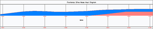
If you look at your Mass Haul diagram (Figure 12-34), you can see that nearly all the earthwork for Frontenac Drive involves Net Cut, which means hauling away dirt. There are measures that can be taken, such as looking at the finished ground and seeing if the profile can be modified to alleviate all of this earth being moved. If you can’t modify the profile, then the Balancing Options come into play.
Figure 12-34: Net Cut shown on Frontenac Drive
3. The Free Haul Distance is presently set for 200′. Change it to 500′ and then click Apply.
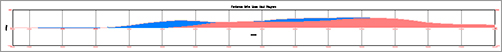
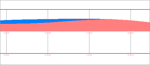
4. Drag the dialog away from the screen to see the changes. The blue color indicates the area of free haul and the reddish color indicates the Overhaul area as shown in Figure 12-35.
Figure 12-35: The Mass Haul diagram with (a) setting free haul distance to 200′ and (b) setting free haul distance to 500′

By changing the free haul distance, you can see the amount of earth that will be moved as part of the contract (free) versus that which is not free.
We can further tweak this amount to cut down on the net cut values, by adding a dump site.
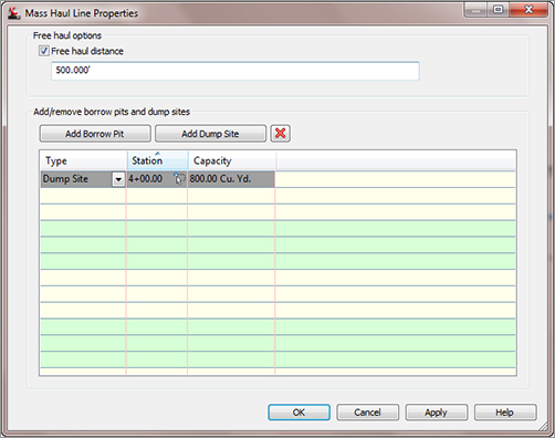
5. Click the Add Dump Site button and make changes shown in Figure 12-36. Click the Apply button and move the dialog out of the way to see the results (Figure 12-37).
Figure 12-36: The Mass Haul Line Properties dialog: adding a Dump Site.
6. You can continue to tweak the station location and the capacity values. Remember, what we are after is a balanced site.
Figure 12-37: Frontenac Drive Mass Haul diagram with the added dump site