
Visualization Sequence and Workflow
You'd be surprised, but many people actually render in the wrong sequence. The workflow for creating compelling renderings is not the same workflow that you use to resolve your design process. If you try to do one like the other, the result is a lot of wasted time and frustration. Trial and error takes too long, and you won't get the desired results (and may even conclude that Revit “can't render”).
Consider a reasonable design process to create a building that moves from intent to content:
- Host components (walls, floors, stair, railings, and so on)
- Family components (doors, windows, and so on)
- Furniture, fixtures, and equipment
- Assembly details and documentation
But if you're rendering in the order of the previous process, your results will be skewed. That's because in order to create photorealistic renderings, you're probably modifying your views in the following order:
- Geometry (host and family components)
- Materials (host and family components)
- Cameras (setting up your views)
- Lighting (lots of errors and rendering, adjusting, rendering, and so on)
- Render (final renderings)
The challenge is that this is not the workflow for creating great renderings. If you're focused on the design process of visualization, the intent to content workflow is more along the lines of the following:
- Geometry (host and family components)
- Cameras (setting up your views)
- Lighting (using matte materials)
- Materials (host and family components)
Yes, this is as simple as it gets: cameras, then lights, and then materials. But in Revit, lights don't usually show up until the building is well resolved, because you're placing lights meant to be the lights in the building, not just for “rendering.” So, the design process is simply out of sequence with the visualization process.
Furthermore, you need to evaluate the lighting neutrally, not with materials to distract you. But as you're placing your content, a lot of stuff already has material assignments. You need to find a way to neutralize the material settings while you figure out lighting. The great thing is that you've already got all the parts to do this from earlier in the chapter. Now you just need to put it all together!
Geometry and Cameras
Geometry and cameras are the first step. You don't want to wait to see your project in perspective until after you've designed it. Unfortunately, you still can't design in perspective views in Revit, but ideally this will change. The point is that you need to be able to experience the space as you're designing, so go ahead and create perspective views of your project so that as you design you can see the results in real time.
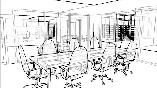
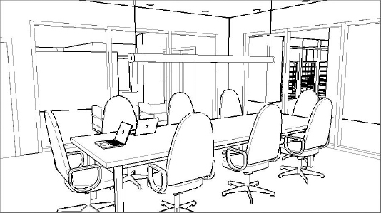
You can either use the project c12_Rendering Workflow.rvt in the Chapter 12 folder or your own file. The workflow is what's important. If you're using the file that we've created, you'll want to start in the RENDER - CONFERENCE ROOM 3D view. As you can see in Figure 12.96, we've already adjusted the shadows and sunlight as well as applied silhouette edges to the view.
FIGURE 12.96 Viewing our project in Hidden Line view

Right away, this isn't a bad view to have in your document set. The linework, subtle shadows, transparency of the glazing, and 16:9 aspect ratio help create a balanced view that doesn't require rendering. So don't be afraid to put these live views into your document set for quick reference.
Another option that you have is to use the Ghost Surfaces option (Figure 12.97). You'll be able to see through solid objects and beyond the immediate space.
And keep in mind that for your preliminary renderings, the abstract phasing settings give everything a nice matte finish (Figure 12.98).
FIGURE 12.98 Abstract phasing setting

Sunlight
Now let's render the view. Keep in mind that the rendered material applied to the Abstract phase override is solid white, so you'll want to turn off the visibility of your curtain panels if you want to see through the glazing. The rendering settings for this view are shown in Figure 12.99.
The reason that we're using Printer as the Output setting is because 300 dpi is sufficient for the printing of this page. And an 8″-wide image will suffice for the anticipated width of this book. Low quality is also sufficient based on our experience, because it's not worth the extra jump in time to render much higher than this first pass.
Figure 12.100 shows the results of the rendering. The scene can be viewed beyond the immediate space of the conference room. Take particular note of the shadows and how the lighting drops off from the edge of a shadow.
FIGURE 12.99 Rendering settings for our view

FIGURE 12.100 Sun Only rendering
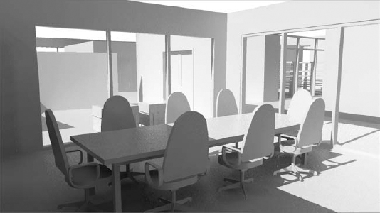
Of course, this image is being rendered with the sun, which doesn't count for interior renderings; it's just a benchmark. So let's turn off the sun and start placing some artificial lights.
Since you're rendering abstractly using a phase override, everything is going to be solid white. But if your “light” source is behind a solid lens, it's not going to render very well.
The best way we've found to handle this (until Revit allows for more analytic rendering) is to create an Object subcategory for the lens that surrounds the light source. Doing so allows you to control the visibility of the lens of the lighting fixture and allow the light to seemingly pass through the object. Unfortunately, this approach will not give the most realistic effect since many lighting effects result from light passing through translucent objects (like lenses or shades). But it's the best you'll be able to do for now to resolve lighting before you resolve materials.
You need to add a ceiling to the spaces. To keep things generic, we've added a compound ceiling to all the spaces (Figure 12.101). It's just a placeholder for your ceiling that will change later. But the important thing is that you don't get hung up centering ceiling tiles during your design process. Rooms will change dimensions, and all that time spent centering will go to waste.
FIGURE 12.101 Ceiling settings
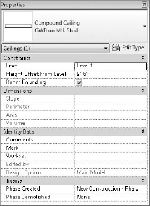
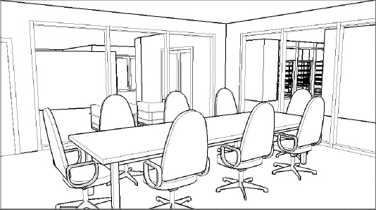
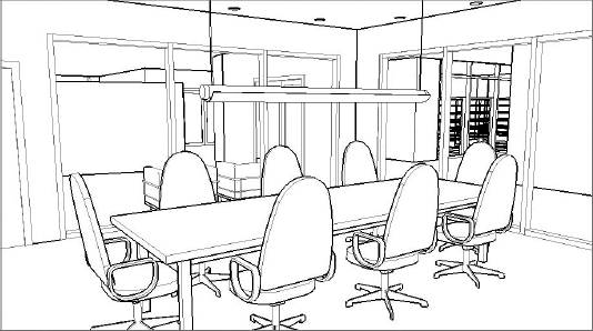
Figure 12.102 shows a Hidden Line view of the space with the materials set to 0 percent transparency. We've also turned the shadows off since it'll just distract us from not having the sunlight influence the view.
Now render the view with the settings shown in Figure 12.103. Notice that we've set the Lighting to Interior: Artificial Only. We haven't placed any lights yet, but the reason that you want to render is to make sure that you don't have any light leaks and to benchmark your rendering. It should be completely black when the rendering completes.
FIGURE 12.103 Rendering Settings dialog box

Artificial Lighting
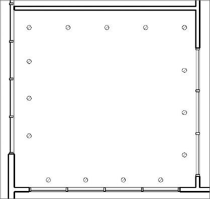
Now load the family Downlight - Recessed Can.rfa and place it in the ceiling and along the two walls, as shown in the reflected ceiling plan (Figure 12.104). The exact dimensions aren't important—just get the idea right.
FIGURE 12.104 Lights in ceiling
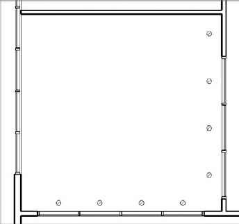
This light family doesn't have a lens, so you don't have to create an Object subcategory for the lens. But before you start to render these artificial lights, we need to explain the process and technique of using light groups.
Light Groups
![]() Sometimes you'll want to isolate the lights that are being calculated and rendered in a particular view. You might want to test the lighting that will result from having certain lights on and others off, just like in a real space. Revit allows you to create light groups for this purpose. Doing so saves you a lot of time compared to turning individual lights off and on manually.
Sometimes you'll want to isolate the lights that are being calculated and rendered in a particular view. You might want to test the lighting that will result from having certain lights on and others off, just like in a real space. Revit allows you to create light groups for this purpose. Doing so saves you a lot of time compared to turning individual lights off and on manually.
By default, whenever you place lights in your project, they're not in any group. They're “unassigned,” just like the lights shown in Figure 12.105.

Besides the assignment for the light group, you also have the option of turning down the Dimming value. This option is great for giving your space a half-lit effect.
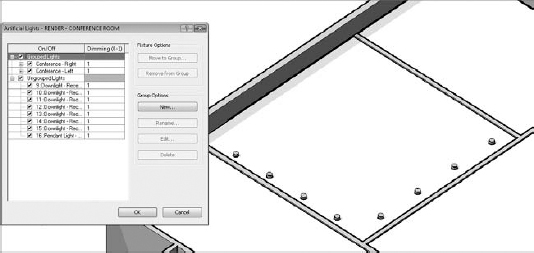
Now let's create two light groups for this space. From the Rendering Settings dialog box, select the Artificial Lights button. Then select New and create the two groups, as shown in Figure 12.106. You're also working from a 3D axonometric view, which will allow you to see the ceiling plan from above. This ability will be helpful for selecting lights from above if necessary.
FIGURE 12.106 Creating light groups
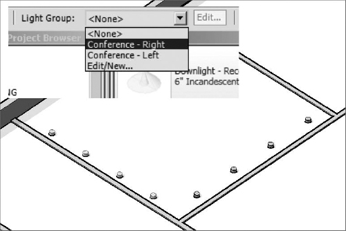
Now let's assign the lights to the groups. Just select the lights and then assign to the light group from the context drop-down menu, as shown in Figure 12.107. Then do the same thing for the lights along the other wall.
FIGURE 12.107 Assigning light groups
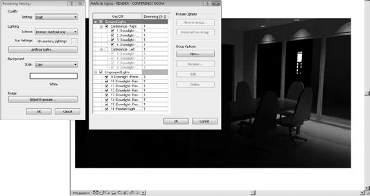
Now return to the interior perspective. Before you start to render the view, let's test the light groups by only rendering the lights in the right group. Figure 12.108 shows the results.
FIGURE 12.108 Rendering light groups
Let's complete the rendering of the space with the other light group turned on. Keep in mind that the more lights you have turned on in your view, the longer the calculations will take, and, therefore, the longer it'll take to render your view. Figure 12.109 shows the results of this second rendering. This figure also illustrates the ability to adjust the exposure in a completed rendering.
FIGURE 12.109 Rendering both light groups
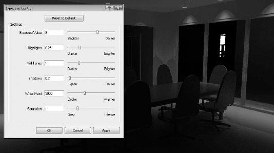
By default, the image will have a rather sepia tone. But removing the sepia tone can be controlled by adjusting the White Point value.
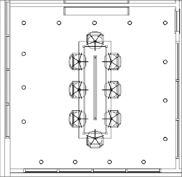
Keep in mind that what you're looking for is how the lighting affects the space. Are the lights too close or too far apart? Go ahead and add more lights, as shown in Figure 12.110.
FIGURE 12.110 Adding more lights
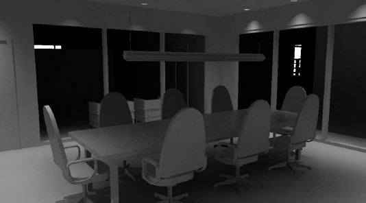
After rendering the space with all the lights, what's becoming apparent is that the lights aren't illuminating the conference table (Figure 12.111). You need to add a nice linear lighting source above the table in order to understand the effect that light will have on the space. Again, it's important that you do this without the distraction of materials.
FIGURE 12.111 Rendering without center lights

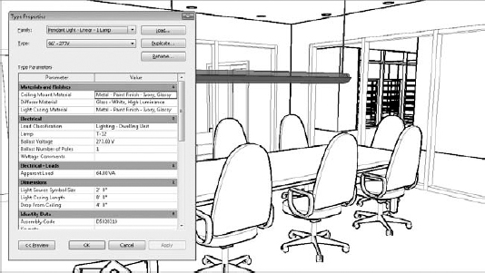
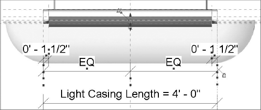
Use the Revit family Pendant Light - Linear - 1 Lamp and place it, as shown in Figure 12.112. A great technique is to use a 3D view that's oriented to the top and then set the view to Wireframe.
FIGURE 12.112 Placing the light in top-oriented 3D Wireframe view
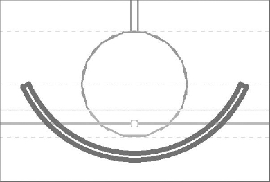
This approach allows you to place elements in the ceiling but also see their context and center the light properly with regard to the conference table and chairs. This time you'll have to put the lens in an Object subcategory. Figure 12.113 shows the light in 3D. The type properties of the light have also been adjusted to allow the light to hang down from the ceiling, as shown.
FIGURE 12.113 Conference table light
The light doesn't have a lens, but you'll make one and then assign it to a subcategory in order to test a rendering with the lens turned off and on. First, check the visibility settings of Lighting Fixtures, as shown in Figure 12.114. Notice the Object subcategories are only Hidden Lines and Light Source. This will change in a moment when you add Lens to the list.
FIGURE 12.114 Lighting Fixtures category and subcategories
![]()
Open the linear light family and go the Right elevation. Then create an extrusion, as shown in Figure 12.115.
FIGURE 12.115 Extrusion sketch
You'll be prompted to select a work plane. Select the work plane shown in Figure 12.116.
FIGURE 12.116 Selecting a work plane

Don't forget to align and lock the finished extrusion, as shown in the front elevation (Figure 12.117).
Also, it is important to note that there's a lens of sorts in the light fixture (Figure 12.118). Delete this geometry from your light, since you've already created a new lens.
FIGURE 12.118 Delete the original lens geometry.

Now reload the light into your project. It will update, as shown in Figure 12.119.
If you render the view, you'll notice that light can't make it past the lens, as shown in Figure 12.120.
FIGURE 12.120 Rendering with a lens
Eventually, the lens will have a translucent material that will allow the light to shine through. But for rendering matte images, you may not want the light blocked so severely. You'll control this by assigning a subcategory to the lens geometry that will allow you to turn off all the lenses in the view at one time, particularly if you use the same naming convention for all the lenses that you put in your lighting fixtures.
Now return to the light family and create a parameter to control the material of the lens. You'll also create and assign the lens to an Object subcategory.
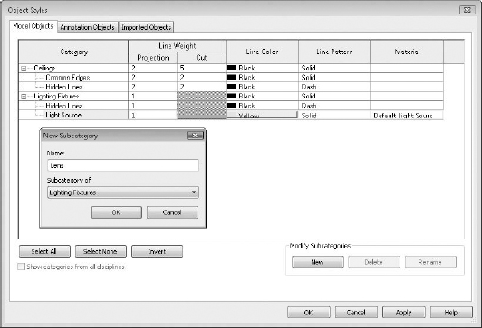
First, select Object Styles from the Modify tab. Then create the Object subcategory, as shown in Figure 12.121.
FIGURE 12.121 Creating the subcategory
Close the dialog box and then select the lens. Now you can assign this geometry to the subcategory that you just created (Figure 12.122).
FIGURE 12.122 Assigning the subcategory

Now that you've created and assigned the subcategory, let's assign the material parameter. You already have the material parameter Diffuser Material from the geometry that you deleted in Figure 12.118. So just assign this, as shown in Figure 12.123, to the new lens.
FIGURE 12.123 Creating and assigning the material parameter

Don't worry about assigning an actual material for now. In practice, it'll only change in the project. So you'll wait to assign it in the project environment rather in the Family Editor.
Now reload the light into the project and go to the visibility settings of the view. There's a subcategory for the Lens part of the lighting fixture. Uncheck this value, as shown in Figure 12.124. The lens is turned off, which is perfect!
FIGURE 12.124 Deselecting the Lens subcategory

Now re-render the view. The results will look like Figure 12.125. Note that the lens for the linear light isn't showing, but this is fine. You're after the lighting effect of the lighting fixture. The lens will come back on when you render with all the materials showing. But before rendering with materials, you need to add some entourage.

If you want your rendering to seem more complete than just a rendering of the building elements, you'll have to add entourage. But you don't want to clutter all your views with the kinds of things that you want to add that will not be part of your document set.
Worksets are great for controlling this part of your project. By creating a workset called Entourage, you'll be able to place your project content on a workset where all of its visibility can be quickly and easily controlled. But before creating and assigning elements to this workset, make sure the workset is turned off by default in other views (Figure 12.126).
FIGURE 12.126 The workset should be turned off in other views.

This means that the entourage will not show up in existing or new views until you turn them on, rather than having to turn this workset off in all present and future views. This will save you a lot of time as you add entourage to your project.
In this case, you're going to add some laptops to the conference table; you must be sure to place them on the Entourage workset (Figure 12.127).
FIGURE 12.127 Adding entourage
Materials
Now that you have determined the right lighting effects using matte materials, you can set the phase back to Show Complete (Figure 12.128). You'll also want to turn on the visibility for the curtain wall panels as well as the lens in the linear lighting fixture and render the view. Keep in mind that with all the new materials, transparency, and reflectivity, it will take quite a bit longer to re-render the view.
FIGURE 12.128 Rendering with material
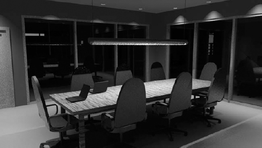
Once you render the view and you can start to see the transparency and reflectivity in the curtain panels, the rendering takes on a much more realistic effect. You can also see the materials in the table and chairs, as well as the lens for the linear light above the conference table.
At the moment, all of the materials that are assigned to the walls in this view are based on the properties of the wall. And creating surface materials for every different wall would result in a very long list of wall types! A better method of assigning materials on a case-by-case basis is to use the Paint tool.
To assign materials to host elements, select the Paint tool on the Modify tab (Figure 12.129).
FIGURE 12.129 Selecting the Paint tool
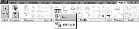
To add a unique material to a wall, hover over the wall and select the surface. To remove a unique material assignment, select the Remove Paint tool, hover over the wall, and select it. The paint material will be removed.