
Using Schedules
You can repurpose many tools in Revit for other uses. Schedules are a great example of this. In Chapter 5, “Managing a Revit Project,” we discussed how to use schedules to perform quality control of your model. Schedules are also a useful tool in sustainable design because they can help track the amount of recycled materials used in the design of a project. If one of your design objectives is to achieve a Leadership in Energy and Environmental Design (LEED) certification (www.usgbc.org/leed), one of the possible points is for the use of recycled materials. Based on how LEED calculates their recycled content requirements (by volume and cost), some of the key materials for recycled content tend to be steel and concrete. Although the schedules created in Revit can't be used for LEED credit submissions in this case, knowing how to calculate recycled content within a project can help steer the project goals during the design phase.
Calculating Recycled Content
In this section's project, let's assume you want to use fly ash, a by-product of steel manufacturing, in your project as recycled content in the concrete mix for your building's structure. Fly ash was first used as a concrete additive in 1929 in the Hoover Dam and can reduce the reliance on quarried materials such as sand. If you want to understand how much recycled fly ash would be used based on the overall volume of concrete in your project, a schedule can keep track of these quantities. We'll show you how to create a schedule that reports the quantity of concrete as well as a calculated value to determine the recycled content as a percentage of the overall volume.
To begin creating this schedule, open the c10-Jenkins.rvt file. You can download this file from the book's companion website (www.sybex.com/go/masteringrevit2012).
- Select the View tab, choose the Schedules flyout, and then select Material Takeoff.
- In the New Material Takeoff dialog box rename the default schedule name to Concrete Takeoff. Make sure the Category selection is set to <Multi Category>.
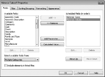
- Now you want to add a couple of fields. Choose Material: Name and Material: Volume from the list on the left. Using the Add button, add them to the column on the right (Figure 10.1).
FIGURE 10.1 Adding fields to the schedule
- Now, still on the Fields tab, click the Calculated Value button. Clicking this button opens the Calculated Value dialog box, which allows you to add custom fields that contain equations. Not only can you leverage some of the features of Revit's database structure, but you can also create fields in your schedules that are formulaically based on other content. In this dialog box, name the value Recycled Content and change the type to Volume.
At the bottom of the Calculated Value dialog box is a blank field for the formula. This field directs Revit on how to perform the calculations. In this project, you want to calculate the volume of fly ash in the model. So, in Revit terminology, you want to create a formula using the Material: Volume field and multiply that against the amount of fly ash you want to use in the construction.
- To create this formula, you can either type the parameter names directly in the Formula field or select the fields you want to perform calculations against using the field selection button
 . If you choose to type your formula in directly, remember that schedules are case sensitive and the parameters will need to be entered that way. For this example, choose the selection button. This will open another dialog box, allowing you to choose fields you have already added to the schedule. Select the Material: Volume field and click OK. Click OK.
 - For this project, your goal is to include 25 percent fly ash in our concrete mixture. Since you have just selected the Material: Volume field, you need to finish the equation. To do this, multiply by 0.25 so your final formula will look like Figure 10.2. Click OK.
FIGURE 10.2 Finishing the calculated value

Now that you have your fields defined, you need to visit the rest of the tabs to define your schedule. The next tab is the Filter tab. So far, you haven't defined what materials you want to see in your schedule—you are currently showing all of them. In this example, you want to filter out all but concrete as a material.
- Switch to the Filter tab and in the Filter By field, select Material: Name. In the drop-down next to that, select Begins With and in the field below the Material: Name, type Concrete. Your filtered schedule should look like Figure 10.3.
This filter will schedule only materials that begin with the name Concrete. Filtering in this way can be more effective than filtering for an exact name because it allows for some variety in the material names. If you are working on a project team and one team member has called the material Concrete – Cast in Place and another team member has created a material called Concrete – CIP, this schedule will include both.
- After you complete the Filter tab, select the Sorting/Grouping tab. In this tab, choose to sort by Material: Name and make sure the option to Itemize Every Instance is unchecked. You also want to select the Grand Totals check box at the bottom of this tab and set the Grand Totals drop-down to Totals Only.
- The last tab you'll need to adjust is the Formatting tab. Select this tab and highlight Material: Volume in the column on the left. From the Alignment drop-down, choose Right and choose the Calculate Totals check box. Repeat these settings for the Recycled Content field, both right-justification and calculating the totals.
Also realize that you can change the unit format of schedule fields that use measured values. If you click the Field Format button, you can change the display units, rounding, or the unit suffix. In this example, try changing the units of the Material: Volume field to Cubic Yards and the rounding to 0 decimal places.
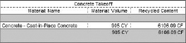
- Now that you've completed all of the formatting and calculations, you can see the results of the schedule. Click OK, and the schedule will generate a single line, as shown in Figure 10.4. The new Concrete Takeoff schedule shows the name of the material, the cubic feet of concrete in the project, and how much fly ash would be (calculated in cubic feet) if you use 25 percent of the volume of the concrete. This schedule will continue to dynamically update as you add or subtract concrete from the overall design, giving you an up-to-date amount of fly ash.
FIGURE 10.4 The Concrete Takeoff schedule

Calculating the Window-to-Wall Ratio
The window-to-wall ratio (WWR) is the percent of glazing you have on any given façade versus the amount of unglazed area. Knowing this percentage can help determine the ideal amount of glazing you will want on each façade to maximize the efficiency of your HVAC system. The desired ratio will vary depending on your building use, latitude (north-south position matters), and façade orientation. Working directly with your mechanical consultant, you can arrive at a target percentage for each primary building façade.
As a general rule of thumb in the Northern hemisphere, it's best to minimize east/west exposure and maximize the north/south exposures if the building site allows. With south exposures, it's easier to control the amount of daylight entering the building with the use of sunshading. In the Northern hemisphere, north-facing walls have limited, if any, direct solar exposure. Since the sun rises and sets on the east/west sides of the building, there is a full arc of daylight (from the peak of the azimuth to the horizon) over the course of the day, making those exposures the most challenging to moderate.
In the sample Jenkins building project, you have an adjacent building proposed next to the existing one. In this scenario, you have been modeling a proposed new building form in Revit's conceptual massing. While doing so, let's assume you've been working with your mechanical engineer to establish the ideal WWR for your primary façade. You now need to calculate the amount of façade you have per floor so you can begin to add glazing to the design.
During conceptual design, the focus was more on the building form than the exact locations of the floors relative to the existing building. Since the form was created as a conceptual mass, the only datum established was the ground plane. To view the sample building addition, open the c10-JenkinsAddition.rfa file located on the book's companion web page. Open the Jenkins Building model and you'll notice the JenkinsAddition mass family has already been placed to the right of the primary façade (Figure 10.5). Now you're ready to create a quick schedule to run these calculations.
FIGURE 10.5 Adding the conceptual mass to the Jenkins model

- The first thing you might notice is that the mass isn't visible in each of the views. You need to turn on the visibility of the mass so you can see it in all the views. On the Massing & Site tab in the ribbon, click the Show Mass button. The button will highlight and stay highlighted until turned off and allow you to see the inserted mass family in all the views.
This command represents a unique feature for masses; activating this button will allow you to see the masses, but remember that if you don't select the Mass category in the Visibility/Graphic Overrides dialog box, it won't show up when you print the views, even though you'll see it on the screen.
Since you didn't add any levels to the mass, you need to project the levels of the original building into the addition and create floors. You want to ultimately create a schedule showing WWR by floor so you have more control over glazing areas. But first you need the floors projected into your mass.
- Select and highlight the mass. The Modify | Mass tab will appear. Click the Mass Floors button.
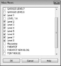
- Selecting this tool will open the Mass Floors dialog box. Since you want one floor in the addition for each floor in the main model, select Levels 1–8, as shown in Figure 10.6. In addition, you're choosing to incorporate a double-height lobby space, so do not select the mezzanine level.
- Click OK and you will see the horizontal planes that are the mass floors. Select the mass and it will be more apparent because the object will become temporarily transparent, similar to Figure 10.7.
FIGURE 10.7 Mass floors have been added to the mass.

- Now that mass floors are established, you can create a schedule that will report some key information about the mass, including the ability to list it by level. You can use scheduling to not only help you find the wall-to-floor ratio (so you can establish WWR) but also the actual area of each new floor plate. To start this, choose Schedules and then Schedule/Quantities from the View tab in the ribbon.
- From the list of schedule categories, choose Mass Floor and click OK to move to the next step.
- Similar to the last schedule you created, you need to select some fields to populate the schedule. Choose the following fields (in order):
- Level
- Floor Area
- Exterior Surface Area
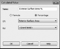
You also want to create a new calculated value. Click the Calculated Value button and name the new field Exterior Surface Area %. Select Percentage from the radio buttons and from the Of drop-down, select Exterior Surface Area (Figure 10.8).
FIGURE 10.8 Creating the new calculated value
- Select the Sorting/Grouping tab and choose Level from the Sort By drop-down.
- For the following fields, change Alignment to Right and select the Calculate Values box.
- Floor Area
- Exterior Surface Area
- Exterior Surface Area %
- The finished schedule for this mass will look like Figure 10.9. You were able to quickly calculate the floor area available by level in the mass as well as the exterior wall area. The Exterior Surface Area % tells you how much of the existing wall area each floor occupies Using this, you can work with your mechanical consultant to better determine how much glazing you should have by façade and floor.
FIGURE 10.9 The finished schedule
