
Formula-Driven Massing
Formula-driven massing can be done in the project environment. But the challenge is that you have to work in context of the project, and all the parameters, formulas, reference planes, and lines can start to get in the way. Therefore, having the option of creating form-driven masses in the Family Editor without the clutter of the project environment can help you focus on what you're trying to accomplish.
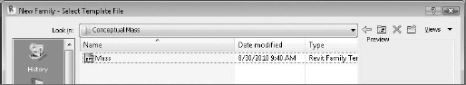
You'll want to make sure that you open the right family template. The Mass template is in the Conceptual Mass folder (Figure 9.110). Don't start with generic model or some other template.
FIGURE 9.110 Starting with the Mass template

Also, turn off the gradient background that's on by default in the graphic display options (Figure 9.111). You can keep this option on if you like, but the images will print better with it turned off.
FIGURE 9.111 Graphic display options

Overall, the UI is not too dissimilar from the project environment. It's like you're creating masses in-place—except that you're not in the project environment, you're in the Family Editor. One significant difference that you can see is that there is a single level and two reference planes, which also define the origin for massing family (Figure 9.112). So, keep in mind that when you reload this family into your project it will update relative to the origin in the family.

Simple Mass Family
In this example, you'll start by creating a simple mass and then will add parameters and test the results. Follow these steps:
- Create this simple mass using model lines on level 1. You can save an extra step by selecting the Make Surface From Closed Loops option (Figure 9.113).
FIGURE 9.113 Selecting the Make Surface From Closed Loops option

- Once you've created the surface in plan, go to the default 3D view and then pull the surface, as shown in Figure 9.114. Again, don't worry about the actual dimensions. Just get the overall proportions close.
FIGURE 9.114 Creating the mass

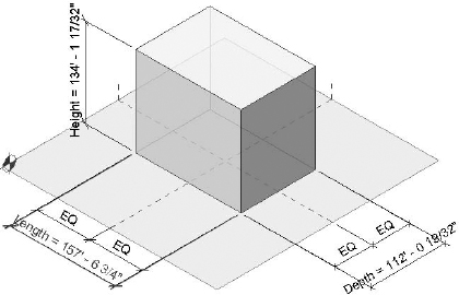
- Now you'll dimension the form. Be sure to maintain a relationship to the insertion point of the mass template by using a continuous dimension string set to EQ (Figure 9.115). Then dimension the overall dimensions in X-, Y-, and Z-directions.
FIGURE 9.115 Adding dimensions

- Now you'll add parameters to the overall dimensions. Simply select a dimension and you'll be shown a context menu that allows you to associate a parameter with the dimension you've just selected (Figure 9.116).
FIGURE 9.116 Associating parameters

- Label this dimension Height, and make it an instance parameter (Figure 9.117). If you had many massing elements of the same type loaded into your project and you wanted to control all of them with the same value, this could be a type parameter. But for this example, an instance parameter is fine.

Once you have all your dimensions associated with parameters, your project should look similar to Figure 9.118. That's because as you associate parameter values with your dimensions, the parameter name will display along with the dimension. This is helpful when you need to know which parameter is associated with which dimension.
FIGURE 9.118 Completed parameters
Now it's going to start to get interesting. Rather than maintain independent instance parameters for each dimension, you're going to associate formulas with the length and the depth values. Go ahead and do this, as shown in Figure 9.119.
FIGURE 9.119 Creating formulas
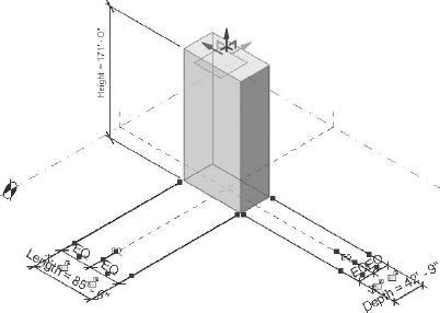
Now your entire mass family can be proportionally controlled simply by adjusting the height parameter (Figure 9.120).
FIGURE 9.120 Proportional form

This proportional control can be accomplished in one of two ways. First, you can select the height dimensional value and change the dimension (Figure 9.121). This is desirable when you want to edit a value to an exact amount.
But in many cases, you'll still want to intuitively control the shape of the form first, and then when you get an idea of what looks right, set the resulting dimensional value to a more reasonable figure. You do so by selecting the top face of the form and pushing or pulling the control arrows until you get it close (Figure 9.122). Notice that each time you release the arrow the form adjusts in all dimensions (since the other dimensions are being controlled by formulas related to the height dimension).
FIGURE 9.121 Adjusting the height numerically

FIGURE 9.122 Adjusting the height intuitively
You can experiment further by creating more geometry at the base of the initial mass:
- Dimension the form, as shown in Figure 9.123.
FIGURE 9.123 Adding a second form

- Associate the dimensions of this second form to the dimensions that you already created (Figure 9.124). What's terrific about this is that as you change a single value, the overall form will proportionally grow or shrink.
FIGURE 9.124 Associative parameters

Ultimately this technique of associating parameters with other parameters is a great way to quickly and easily maintain important and interesting formal relationships between masses. Notice how the two masses in Figure 9.125 are barely intersecting near the base of the horizontal form.
FIGURE 9.125 Proportional forms
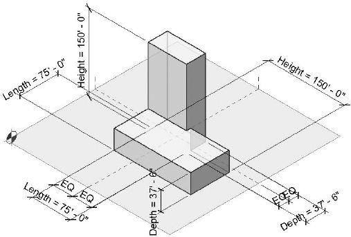
But when you modify the height of the vertical element, both forms grow accordingly (Figure 9.126). The intersection becomes much more noticeable, and if you continued to increase the height of the vertical mass, the intersection would eventually move beyond the face of the horizontal mass. If you want to download this family, look in the Chapter 9 folder for the file c09_Parametric_Massing_Simple.rfa.
FIGURE 9.126 Modifying parameters

Overall, simple parametric masses can be created quickly and easily in the Family Editor as a mass. But in some cases having access to the old, pre-2010 geometry tools would be great. As you may be aware, there's a built-in solution for this. But since this book is about mastering Revit, we're going to show you how right now.
Generic Model Mass Family
A lot of users (the authors included) really miss the ability to use the old geometry tools to create masses. Although it's possible to create parametric generic forms in the Family Editor, when you place them in the project they're still generic elements. You can assign standard walls, curtain walls, and roofs to the faces. But you can't add patterns, create mass floors, or even schedule the results as a mass. We think this is unfortunate! Yes, being able to modify the edge and vertex of a new massing element has some advantages. But many of us early adopters knew how to create the same resulting shape using the old, familiar toolset. So, if you like the old pre-2010 tools, here's how to use them to create project masses in Revit 2012:
- Open a Generic Model template (Figure 9.127). You're going to create a flexible, parametric form and then “trick” Revit into thinking that this generic family is a mass.
FIGURE 9.127 Generic Model template

You won't be able to trick Revit by creating a generic model family and then converting it to a mass by changing the family category (Figure 9.128). But there's another way, so just hang in there!
FIGURE 9.128 Message box explaining you can't change the category

- Go to a floor plan reference level view in your family. Begin by creating a reference line (not a reference plane), as shown in Figure 9.129. Note that the reference line is drawn from the intersection of the reference planes in an upward direction.
FIGURE 9.129 First reference line

- Draw another reference line in a downward direction (Figure 9.130). These reference lines will control the angular “twist” in our eventual family.
FIGURE 9.130 Second reference line

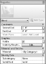
Now you're going to create a blend (Figure 9.131) that is associated with the reference lines you just created. The bottom of the blend will be associated with the first reference line and the top of the blend will be associated with the second reference line.

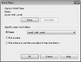
- Before you start to sketch the bottom shape for the blend, it's important that you select the reference line as your work plane (Figure 9.132).
- Select the upper reference line as shown in Figure 9.133.
- Sketch a rectilinear form, as shown in Figure 9.134. The exact dimensions aren't important. What is important is that the dimensions are equally distributed between the reference lines. You also want to give parameters to the overall dimensions. We've called the instance parameter BW (for bottom width) and assigned the parameter to both the overall dimensions.
- When you add the parameter, assign the settings shown in Figure 9.135.
- Select Edit to sketch the top of the blend. But make sure that you set the bottom reference line as the work plane (Figure 9.136). Doing so allows you to control the angular twist of the blend when it's complete.
FIGURE 9.133 Selecting the upper reference line

FIGURE 9.134 Bottom with dimensions

- Essentially you're going to repeat the previous step for the lower sketch for this upper sketch. Equally distribute the overall dimensions and give the parameters as shown in Figure 9.137. We've called these parameters TW (for top width).
FIGURE 9.135 Use these instance parameters.
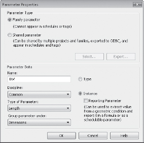
FIGURE 9.136 Setting the work plane

FIGURE 9.137 Top width parameters and sketch

- Now that the base and top width parameters have been set, you can add parameters to control the height of the blend. Do this by selecting the button to the right of the second end constraints (Figure 9.138).
FIGURE 9.138 Adding the height parameter
- Add the parameter H (for height), as shown in Figure 9.139. Now select Finish Family to complete the blended form.
FIGURE 9.139 Instance parameter for the height

- You should take a moment to test that the reference lines control the top and bottom sketch of the blend (Figure 9.140). Simply select the reference line to highlight it and then move the end of the reference line. The other end remains associated with the intersection of the insertion point and the top and bottom sketch rotate.
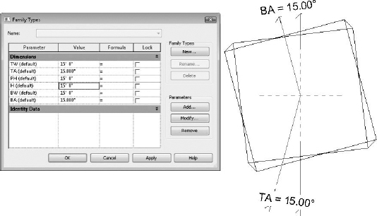
- From a plan view, move the reference lines so that they're no longer on top of the reference planes. Now you can add angular dimensions between the reference line and the reference plane (Figure 9.141). Furthermore, you can add parameters to control the top and bottom angles of the blend. We've called these instance parameters BA and TA (for bottom angle and top angle, respectively). Figure 9.141 also shows all the parameters that control this blend. Go ahead and test them.
FIGURE 9.140 Twisting the blend with reference lines
FIGURE 9.141 Angular parameters
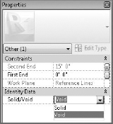
- You're going to use the edges of this blend to drive the geometry that you're going to create. But since you don't want to see this blend, you'll turn it into a void (Figure 9.142).
FIGURE 9.142 Turning a solid into a void
- After you change the solid blend into a void, it will look similar to Figure 9.143.
FIGURE 9.143 The resulting void blend

- You'll begin to create the sweep that will create our building mass in the project environment. That's right—the building mass is going to be based on a circuitous sweep! Select the Sweep function from the Forms tab (Figure 9.144).
FIGURE 9.144 Selecting the Sweep function

- Now select Pick Path (not Sketch Path) in order to select the edges of the blend previously created (Figure 9.145).
FIGURE 9.145 Using the Pick Path tool

- Pick the edges of the blend, as shown in Figure 9.146. Note the location of the sketch plane along the lower rear edge. This is because it is the first edge selected.
FIGURE 9.146 Selecting the edges of the blend

- Once you have selected the edges of the blend, click the Select Profile option and select Edit Profile (Figure 9.147). Doing so allows you to sketch the profile in direct context of the selected edges.
FIGURE 9.147 Selecting the Edit Profile option

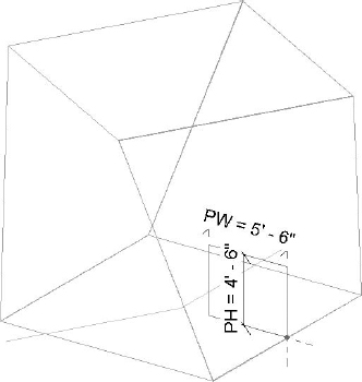
- After you've sketched the profile as shown, be sure to add parameters to the profile width and height. We've called the instance parameters PW and PH, respectively (Figure 9.148).
FIGURE 9.148 Adding parameters to the profile width and height
- Finish the sketch and the sweep, and the profile will generate as shown in Figure 9.149.


Now it's going to start to get really interesting! You'll use this generic model family in the project environment and Revit will think it's a mass:
- Open a new project and begin by creating an in-place mass. We've named the mass as shown in Figure 9.150.
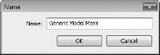
- While still in the In-Place Mass mode, go back to your family and load the generic model into your project environment. Place the generic family as a component into your project. Again, this is being done during In-Place Mass mode.
- Flex the parameters as shown in Figure 9.151. What started as a small parametric form the size of a room is now over 100′ (30 m) tall!
FIGURE 9.151 Changing parameter values

- Now finish the in-place mass. Even though this is a generic model family, because you've placed it during In-Place Mass mode, Revit treats it as a mass.
- Add the levels as shown in Figure 9.152 so that there are levels that extend across the entire elevation of your massing.
- Return to In-Place Mass mode and select the generic mass, and you'll be able to add floor area faces to your massing (Figure 9.153).
- If you hover over the face and tab to select it, you'll also be able to associate patterns and pattern-based components with your generic massing family (Figure 9.154). This is because Revit is now treating it as a massing element in the Mass category.
FIGURE 9.152 Adding levels that extend across the elevation of your massing
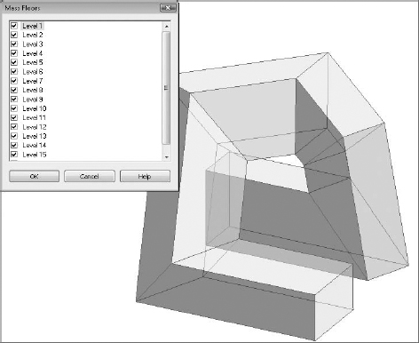


Figure 9.155 shows four perspective views of the completed massing study, all created with the familiar geometry toolset.
FIGURE 9.155 Perspective views

We've also rendered the model as shown in Figure 9.156. The results are quite interesting, and you'll still have the ability to modify the underlying parametric family and then rehost the faces. You'll also be able to schedule the volume, surface, and floor area of the mass.
FIGURE 9.156 Rendering of the generic massing project

You can download and further investigate the files that were used to create this exercise in the Chapter 9 folder. Download the project file c09_Parametric_Generic_Massing.rvt, which contains the in-place massing and the loaded generic element.
Now let's begin to investigate how to create parametric massing in the Family Editor using the conventional massing tools.
Complex Mass Family
Let's start by opening a conceptual massing family template, as shown in Figure 9.157. You'll also turn off the gradient background in this section.
FIGURE 9.157 Conceptual massing template
In the past, the ability to parametrically control objects in the massing editor was done using reference planes and reference lines. What is great is that Revit introduced reference point elements in 2010. Point elements allow for Cartesian x, y, z, as well as rotational control.
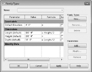
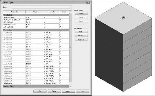
With all complex and parametrically controlled families, we think it's best to get the rules down first. In this case, the rules are the parameters and formulas that will control a twisting, tapering tower. Open the Family Types dialog box and enter the values and formulas shown in Figure 9.158. Doing this first will save a lot of time and frustration from having to name parameters. You'll only need to assign parameters as necessary.
FIGURE 9.158 Family Types dialog box

You're going to create the first rectilinear form on the first reference level. As you do this, be sure to use reference (not model) lines (Figure 9.159).
FIGURE 9.159 Using reference lines

Dimension the sketch twice, being sure to use the EQ function to evenly distribute the sketch at the center of the reference lines at the origin. When finished, associate both overall dimensions with the W0 parameter that you've already created (Figure 9.160). W0 is shorthand for the width dimension on the 0 level.
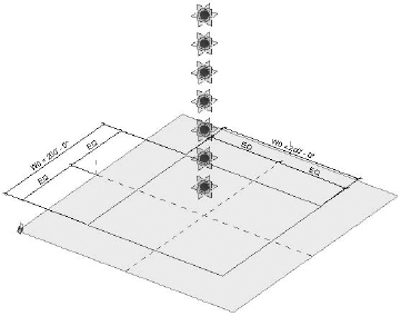
While in the same view, place seven point elements at the intersection of the default reference places. Each time you place a point element, you'll get a warning about overlapping point elements, as shown in Figure 9.161. You can ignore these warnings.
Now go to your South elevation and select just one of the point elements that you placed in plan. You can elevate it manually by dragging the up arrow to move it away from the other overlapping point elements (Figure 9.162).
FIGURE 9.160 Dimensioned reference lines

FIGURE 9.161 Ignore this warning.
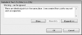
FIGURE 9.162 Moving the point element

But when you select the arrow, you'll also have the option to parametrically associate the point element with one of the seven instance parameters that you've just created (Figure 9.163). The L parameters refer to the level number of each of your point elements. The first point element is L1 since it is reference level 1.
FIGURE 9.163 Adding a parameter to the point element

Now do this for all your point elements. When you are finished, the South elevation will look similar to Figure 9.164.
FIGURE 9.164 The South elevation will look like this.

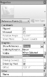
Right now the point elements are just spherical nodes. Their reference planes are not visible. Let's change that by selecting all of them and then selecting Always next to the Show Reference option in the Graphics panel of the Properties dialog box (Figure 9.165).
FIGURE 9.165 Selecting Always next to Show Reference
The reference planes of your point elements will now be visible, as shown in Figure 9.166.
FIGURE 9.166 The reference planes will now be visible.
Select the lowest point element and associate it with the parameter that will control its angular rotation (Figure 9.167). Select the button next to the rotation angle and associate it with the A1 instance parameter.
FIGURE 9.167 Setting the rotation angle

Now set the active work plane to the point element, as shown in Figure 9.168. Then sketch a rectilinear shape as shown. Dimension it just like you did for the sketch at level 0. Dimension both directions with an overall dimension as well as an EQ dimension. Finally, associate the overall dimensions with the W1 parameter, which will control the width of the sketch.
FIGURE 9.168 Creating the second sketch

Systematically do this for each of the point elements, being sure to set the respective reference plane before you sketch the shape with reference lines. When you have finished this for all seven point elements that you created, your view will resemble Figure 9.169.
For clarity, we've hidden the dimensions in the view so that you can see all the reference lines and point elements.
FIGURE 9.169 Reference lines and point elements

Now select all the reference lines and select Create Form. Although this will look like a simple extrusion, it's actually a blend with many profiles. Open the Family Types dialog box and begin to test the results before loading the family into the project (Figure 9.170).
FIGURE 9.170 Testing our form and instance parameters
Test the parameter that controls the distance between levels by increasing the HPL instance parameter (which stands for height per level).
Now test the ability of the shape to taper (Figure 9.171). Do so by increasing the WCPL instance parameter (which stands for width control per level).
FIGURE 9.171 Increasing the WCPL instance parameter

Next, test the parameters that control the amount of angular twist per level (Figure 9.172). Do so by increasing the APL parameter (which stands for angle per level).
FIGURE 9.172 Increasing the APL parameter

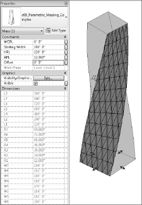
Now that you've tested the massing in the family environment, open a new project and start to create a new, in-place mass. Then place this family into the project during In-Place Mass mode. When you select the massing family, you'll be given access to all of its parameters in the Properties dialog box, as shown in Figure 9.173. You can quickly and easily test the massing parameters in order to significantly increase the height, width, taper, and incremental rotation of the massing family.
FIGURE 9.173 Flexing the parameters

Adding patterns to the face of your mass should be second nature if you've been doing all the exercises in this book. Simply tab to select the face, and then apply the pattern as shown in Figure 9.174.
FIGURE 9.174 Adding patterns to the face of your mass
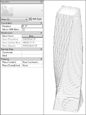
Floor area faces are another simple matter. Provided you have enough levels in your project, select the mass and then select the levels that you want to associate with the floor faces (Figure 9.175).
Creating interesting and complex massing studies that can be parametrically controlled isn't just a skill developed over time. The rules that you develop to make and reiterate your design are also carefully considered aesthetic choices to make decisions rather than blobs! To see this file, go to the Chapter 9 folder and download c09_Parametric_Massing_Complex_Project.rvt. Be sure to turn on Show Mass if it's not turned on when you open the file.