
Importing 2D Data
In this section, we will discuss how to import 2D CAD data from platforms such as AutoCAD (DWG) and MicroStation (DGN) or in the generic Drawing Exchange Format (DXF). You can also use files from other software platforms, but only if they are DWG, DGN, or DXF format. Most commercially available CAD programs are able to export in DWG or DXF format.
There are two fundamental ways 2D CAD data can be used with respect to a building project's floor plans, ceiling plans, or site plans:
- Using 2D data as backgrounds for BIM conversion
- Integrating 2D data with the model
Backgrounds for BIM Conversion
In this situation, we will assume that 2D CAD data will be linked into the Revit model to be converted into building elements. Although the positioning of the files is important, the color and line weights of the imported data are not.
To begin the next exercise, you will need the files c08-Plan01.dwg and c08-Start.rvt. You can download these files from this book's companion web page. After downloading, open the c08-Start.rvt file, and activate the Level 1 floor plan.
- Switch to the Insert tab and select Link CAD from the Link panel. Browse to the file c08-Plan01.dwg.
- In the Link CAD Formats dialog box, set the following options:
- Current View Only: Selected
- Colors: Invert
- Layers: All
- Import Units: Auto-Detect
- Positioning: Auto – Origin To Origin
LINKING VERY LARGE CAD DATA
Use caution when attempting to link or import CAD files with vector data very far from the origin. Revit has distance limitations on imported vector data that—if exceeded—may result in a warning, as shown here:
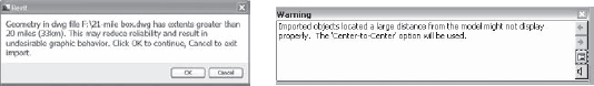
Notice in the warning message that Revit will automatically use Center To Center positioning if the distance limitations are exceeded. This will preclude you from using the origin of the linked file for Origin To Origin placement. If you must link data that is physically larger than a 20-mile cube—which may occur in projects such as airports or master plans—you should separate the data into smaller portions before linking. If the data is smaller than the 20-mile cube but is located farther than 20 miles from its origin, an alternate origin should be coordinated with your project team, and the data should be moved closer to the origin.
Coordination
If you need to use 2D CAD data as an integrated component of your team coordination, different settings become important. Examples of these types of scenarios might include the following:
- Showing light fixture layouts from a lighting designer
- Integrating landscape design into a site plan
- Reusing existing CAD data for a renovation project
Most of the settings and procedures for conversion apply to the coordination process; however, color and the placement visibility will be different. Because this data will be included in the output from Revit, you will always want the color option to be set to Black and White in the options during linking. It is also likely that some sort of background plans will be exported from the Revit model for use in coordination by one or more consultants using a CAD-based program. The data returned in this process may still contain the background information originally exported from Revit; thus, we recommend agreement to a standard that establishes unique layers for the consultants' content. This will help you select layers to be loaded when linking your consultants' files into the Revit project.
Use these options when linking CAD files into Revit for plan-based coordination:
- Current View Only: Selected if data is needed in one view; unselected if data is needed in many views
- Colors: Black and White
- Layers: Specify (choose only designated layers to isolate consultants' content)
- Positioning: Auto – By Shared Coordinates
If Current View Only is not selected, the 2D CAD data will be visible in all other views. This could be a nuisance in views such as sections and elevations; however, you might find it useful to visualize the data alongside the Revit model, as shown in Figure 8.7.
FIGURE 8.7 Existing CAD data integrated with the Revit model

Details
Your company's CAD detail library does not need to go to waste when you implement Revit. External CAD data can be linked into drafting views, allowing you to leverage the powerful view coordination tools within Revit. Entire sheets of CAD details can be inserted to reduce the number of linked files Revit has to reconcile; however, we recommend linking one detail into each drafting view and utilizing Revit's ability to automatically manage the view references with callouts, sections, and detail views. You may also want to name these drafting views with a unique prefix to help keep track of where any linked CAD data might reside. For example, a drafting view might be named CAD-Roof Detail 04. Also refer to Chapter 4, “Configuring Templates and Standards,” for additional information on view organization.
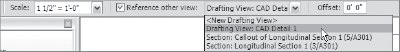
In this exercise, you will create a drafting view into which a single CAD detail will be linked. This view can be referenced throughout your Revit model using a section, callout, or elevation view with the Reference Other View option selected in the Options Bar, as shown in Figure 8.8.
FIGURE 8.8 Creating a view as a reference to a drafting view
To begin this exercise, open the c08-Jenkins.rvt file. You can download this file and the associated CAD file (c08-Detail.dwg) from the book's web page.
- Switch to the View tab and select Drafting View from the Create panel.
- Name the new drafting view CAD Wall Detail 1, and set the scale to 1-½″=1′-0″.

- Switch to the Insert tab and select Link CAD.
- In the Link CAD Formats dialog box, navigate to the c08-Detail.dwg file and set the following options:
- Colors: Black and White
- Layers: All
- Units: Auto-Detect
- Positioning: Auto – Center To Center
- Click Open to complete the command. If you don't see the linked detail in the drafting view, use Zoom To Fit in order to reset the extents of the view.
- Open the Section 2 view from the Project Browser, and zoom to a portion of the view where a floor meets an exterior wall.
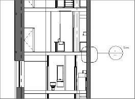
- From the View tab, select Callout from the Create panel, and select Reference Other View in the Options Bar (similar to Figure 8.8). Choose Drafting View: CAD Wall Detail 1 from the drop-down list. You'll see the result shown in Figure 8.9.
FIGURE 8.9 Callout created to reference a drafting view containing a linked CAD detail
- Double-click the callout head, and you will be taken to the drafting view with the CAD detail linked in the previous steps.