Modeling for Construction
In Mastering Autodesk Revit Architecture 2011 (Wiley, 2010), we wrote about a technique to manually model each individual layer of a wall assembly to better understand the construction of the wall. This technique also supported more enhanced phasing and even construction sequencing simulation using a program such as Navisworks Simulate. The drawback to this approach was the complexity in managing far more building elements, and it was usually only used by the builder.
We are pleased to see some new functionality in Revit 2012 that supports a more interactive and flexible approach to construction modeling. The first addition is the ability to create parts, which are individual subsets of more complex layered elements such as walls and floors. The other addition allows you to generate assemblies, segregated subsets of the project model with their own associated views, annotation, and sheets.
Although the title of this section is “Modeling for Construction,” these new tools are more about adaptive reuse of the model, which is hopefully a step in the right direction. The potential to minimize data loss between the design and construction stakeholders of a project can start to change how we approach collaboration and delivery of our buildings.
Creating Parts
Parts are designed to aid the user in subdividing larger model elements into smaller components for construction planning. Each part maintains a persistent relationship with the elements from which it was derived, and it can be subdivided into smaller parts if necessary. Parts can be generated from walls, floors, ceilings, and roofs, as long as they are of consistent thickness. They also have their own properties, such as volume, area, and height; as such, they can be scheduled independently of their original elements.
While it is likely this tool will also be used by designers to customize architectural elements, we will only discuss the workflow intended for the builder. In Mastering Autodesk Revit Architecture 2011 we wrote about a process of building up wall assemblies by joining separate wall types that represent each component of the wall structure. This may have worked well for the builder's needs, but in some cases it did not support the needs of the architects to produce a lightweight model that is easy to manage throughout the design process. If the architect was not coordinating directly with the builder, it was common for the design model and the construction model to be developed as two separate efforts.
In this section we will show you the basic workflow for creating and dividing parts. We encourage you to explore this new tool further and to provide feedback to Autodesk on your findings.
- Open the file c22-Parts.rvt, which you can download from this book's web page.
- Activate the default 3D view if it isn't already open. Notice that each of the wall, floor, ceiling, and roof elements in this sample model is composed of one object. A section box has been activated in this view that is exposing the layers within each assembly.
 Select the floor at Level 2. On the Create panel in the contextual tab of the ribbon, click the Create Parts button.
What you may not immediately notice is that the original object has been visually replaced in the current view by the parts representing each layer of the floor assembly. It is still in the project model—it has not been deleted.
There is a new view property named Parts Visibility whose default value is Show Parts. This means that if parts have been created for any object, they will be displayed instead of the original. This property can also be set to Show Original or Show Both.
- In the Project Browser, right-click on the default 3D view and choose Duplicate View and then Duplicate. Rename the copy of the view Original Model.
- From the Properties palette, find the Parts Visibility parameter and change it to Show Original.
- Go back to the default 3D view and repeat the process of creating parts for the wall, the ceiling, and the roof in the sample model.
In the previous exercise, you created an alternative way to view your model that begins to explore constructability. Without additional modification, you can start to interact with these individual components by examining their properties or even hiding them or overriding their graphic display.
MODIFYING PARTS
In addition to creating parts from original model elements, you can divide these parts into smaller ones. You can even change the phasing properties at the part level and use grips to modify the extents of the parts. Let's begin with an exercise to divide some parts using planes and sketched lines.
- Go back to the default 3D view and select the top part of the floor at Level 2 for which you created parts. This will be the layer representing carpet.
- From the Part panel in the contextual ribbon, click on Divide Parts. You will enter a sketch mode where you can either select intersecting datum or draw your own dividing lines.
- Click the Intersecting References button in the contextual ribbon. You are presented with the Intersecting Named References dialog box (Figure 22.14). From the Filter drop-down, select All and notice that you can choose from levels, grids, or named reference planes. If a reference plane has not been named, it will not appear in this list.
FIGURE 22.14 You can use datum as one way to divide parts.

- Check the boxes for the two reference planes named xPlane1 and yPlane1. Then click OK to close the dialog box.
- Click the green check in the contextual ribbon to finish the edit mode.
After you complete the process for dividing the part, you will notice the part has now become four separate pieces. To experiment with how the parts maintain their relationship to the original object as well as the intersecting reference planes, go to the Level 1 floor plan and move the reference planes around, but try to keep them within the boundary of the sample floor. When you return to the 3D view, you will see that the divisions stay synchronized with the reference planes.
- Activate the Ceiling Plan for Level 1. Select the Gypsum Wall Board part on the bottom of the ceiling below the Level 2 floor.
You can make sure you have the correct part selected by examining the Properties palette. The category filter at the top should display Parts (1) and the Material parameter should indicate Gypsum Wall Board.
- Click the Divide Parts button in the contextual ribbon. Draw a diagonal line across the part from left to right, as shown in Figure 22.15.
FIGURE 22.15 Sketch a line to divide a part.

If you need to sketch lines to divide parts, the lines do not have to be in closed loops, but they must intersect the boundaries of the part. Keep in mind that if the original element is edited so that its boundaries extend beyond any sketched part divisions, the part divisions will be deleted.
- Activate the default 3D view and orbit the model so you can select the inside face of the wall. Select the part of the wall that would represent the gypsum wall board at the interior face of Level 2.
- From the Properties palette, find the parameter named Show Shape Handles and check the box. You will see triangular shape handles on all four sides of the part, as shown in Figure 22.16. Drag the top shape handle down to indicate that the gypsum wall board is not to be installed to the full height of the wall assembly.
FIGURE 22.16 Use the Properties palette to enable shape handles for parts.

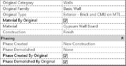
There are several other ways you can interact with parts in your project model. Select any of the parts and observe the Properties palette. You will see that you can override each part's material, phase created, and phase demolished (Figure 22.17).
FIGURE 22.17 Some part properties can be overridden.
BE AWARE OF THE NEW PARTS CATEGORY
Because parts are a new type of element in Revit, you should pay careful attention to how they might affect your views and view templates. Take a look at the Visibility and Graphic Overrides for any view and you'll see that Parts is now listed as an object category. This means that once you create parts for a model element—whether the original object was a floor, ceiling, wall, or roof—the parts are all treated as a singular type of object. For example, if you have surface patterns for floors hidden in a view and you create parts for a floor, the surface pattern will appear again unless you have hidden surface patterns for the Parts category as well.
SCHEDULING PARTS
Another valuable aspect of using parts is the ability to schedule them—essentially a cleaner way to generate material takeoffs. You can create a parts schedule in the same manner you would for other object categories. Go to the View tab, click Schedules ![]() Schedule/Quantities, and choose the Parts category.
Schedule/Quantities, and choose the Parts category.
Select the Fields tab of the Schedule Properties dialog box, and you will notice the potential of the available fields (Figure 22.18). With a part schedule you can report the original category of the object along with the part material and the usual geometric information.
FIGURE 22.18 A part schedule has access to some unique fields for reporting.

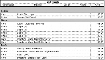
There is also a field named Construction that indicates whether the part was derived from a Core layer or a Finish layer. This field can then be used as a filter or sorting criterion in your schedule. An example illustrating the results of a part schedule is shown in Figure 22.19.
FIGURE 22.19 An example of a completed part schedule
Creating Assemblies
An assembly is a new way to organize related elements within your Revit project. The feature is designed to help users track and schedule a collection of elements as a single entity. In the case of pre-cast concrete, for example, a column made of multiple families including reinforcing bars, mounting hardware, and corbels can be collected into a single assembly.
As you identify objects to be included in an assembly, you can also choose from a variety of views in which to document the element in isolation from the rest of the project model. A collection of assembly views can be thought of as shop drawings. Let's take a look at the workflow for creating an assembly.
In the following exercise, you can use any sample model to illustrate the process of creating assemblies.
- In any view of your project, select a few model elements. Try to pick a few that are relatively close to each other.
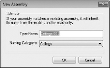
 From the Create panel in the contextual ribbon, click Create Assembly. You will be prompted to name the new assembly (Figure 22.20).
FIGURE 22.20 Create a name for the new assembly.
If you selected objects of different categories such as a wall and a ceiling, you have the opportunity to select which category the assembly will inherit. Choosing one category or the other does not seem to have an effect on the functionality beyond the organization that is exposed to the user.
When you create a new assembly, Revit automatically determines if another identical assembly exists in your model. If one exists, the new assembly inherits the name of the identical assembly. In a somewhat similar situation, if you were to create copies of an assembly throughout your project, the matching assemblies would function in a similar way to groups. The fundamental difference between assemblies and groups is in the propagation of changes. If you have identical assemblies in a project and you change one of them, Revit changes the name of the modified assembly and treats it as unique.
CREATING ASSEMBLY VIEWS
After you have created an assembly, you can create a series of views that are dedicated to that assembly. In other words, you will see only the elements included in the assembly within these views. In addition to plans, sections, and 3D views, you can generate parts lists and quantity takeoffs for an assembly.
To generate assembly views, select an assembly in any view and click Create Views from the Assembly panel in the contextual ribbon. You are prompted with a dialog box in which you choose the views assigned to the assembly (Figure 22.21).
After you click the OK button, you will find the assembly views at the bottom of the Project Browser. Under the Assembly grouping you will find each assembly listed with all of the associated views (Figure 22.22).
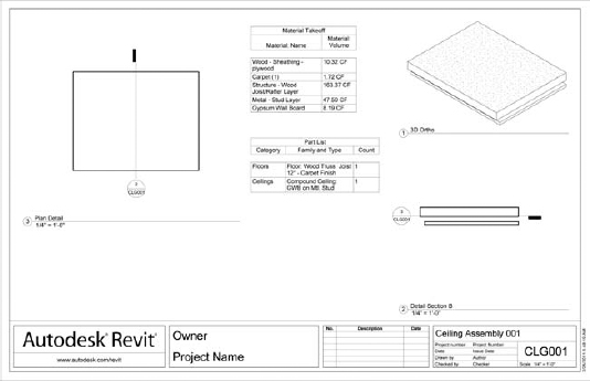
Although sections are automatically placed for the included elements, the individual views are not placed on the assembly sheet. To do this, activate the sheet within an assembly and then drag and drop the views onto the sheet. Note that you can only place views from the related assembly. You cannot drag a view from a different assembly onto the sheet of another. An example of views compiled into an assembly sheet is shown in Figure 22.23.
FIGURE 22.21 Select views to be created with the assembly.
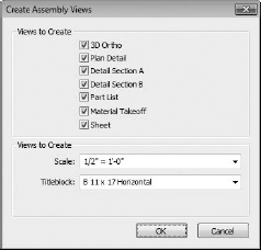
FIGURE 22.22 Assembly views are found at the bottom of the Project Browser.
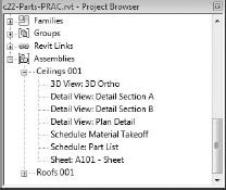
FIGURE 22.23 An example of a simple assembly sheet