
Documentation
With complex geometries, construction documentation of building elements in Revit can sometimes be difficult. For our project, the slanted elliptical curtain wall was particularly challenging. Since Revit cuts the floors at a height above the level but we want our dimensions for a sloped façade to be right where the slope is at the floor line, we thought we were going to have to either make some complicated plan regions or draft in lines to dimension to. Both of those solutions are bad ones, with a lot of extra work anytime the building changed. Here are some other suggestions for documenting complex building forms using Revit.
Generic Model Line Families, Part 2 To help manage change in building form, and get dimensions for the mullions, we started making a spreadsheet that would calculate the lengths automatically and any elevation.
However, we realized this approach could be another good use for those Generic Model line families we had constructed to control the mass (Figure 21.36). The line families work just as well in the project to give us something intelligent and parametric to dimension to, and save us time on changes. In Figure 21.36, the blue lines are the same Generic Model line family used in the mass to define the ellipse, with one little change: It uses the formulas from Microsoft Excel to calculate its exact size at any elevation in the project. The following is for the major axis:
IF(Use Elevation for Axis Size, (Base Major Axis + Elevation above Plaza × ((Top Major Axis - Base Major Axis) / Top Ellipse Elevation)), Manual Major Axis)
FIGURE 21.36 Ellipse dimensioning

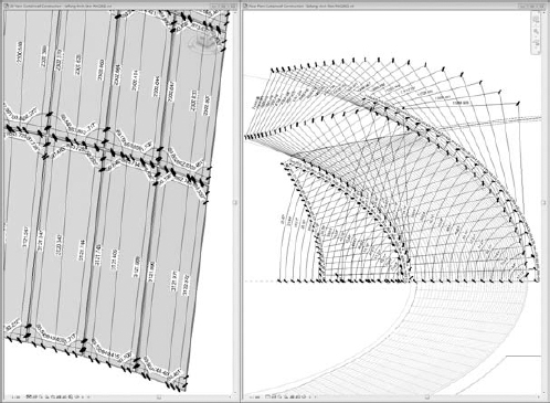
Is It Really Flat? We also ran into a challenge proving that the panels in the sloped elliptical curtain wall were flat. First we used dimensioned 3D views to document the individual panels in the system, as shown in Figure 21.37.
FIGURE 21.37 Panel dimensioning
The second was a trick Zach Kron and Robert Manna demonstrated at Autodesk University 2010. An adaptive component can be applied to a divided surface and displays a color if something is planar or is warped. This approach is a great way to leverage families in Revit for constructability analysis. Figure 21.38 shows a series of shapes with variations in ellipse and circular forms. Any panel that is dark blue is perfectly flat. Red is beyond the maximum deflection criteria. The other colors are in between, with cyan meaning slightly warped, green in the middle range of allowable deflection, and yellow at the extreme end of allowable deflection. You can also see our mass in the background, with all blue panels verifying that it too is made with flat panels. This way of analyzing geometry and illustrating it graphically is a fantastic communication tool for working with owners and contractors.
FIGURE 21.38 Adaptive planar component
