
Generic Model Outline Families
Complex building forms frequently require different individual forms joined to or cut from one another to create the final building shape. Just as in any other family, the more complex it gets, the more difficult it is to properly constrain. Each form element requires its own set of constraints and parameters and sometimes requires additional constraints on the original form element to keep it stationary when the second element is flexed. Multiply this by 10 form elements, and you can imagine how difficult it could be to keep control of the family.
Fortunately, there are alternatives to this highly complex environment. Nesting families into other families simplifies what would otherwise be a difficult family to make. Almost every piece of content has at least one nested family in it. In the massing editor, you can nest any category of family into the host massing family. For our examples, we'll be using the Generic Model template to create the basic outlines of our forms.
The “outline” part is important. If you aren't used to the massing editor, you need to understand that all the shapes it can make are based on combinations of 2D outlines. So, in trying to create a nested family to simplify the form, you are really attempting to create the outlines of the extrusion, loft, revolve, or whichever primitive you are trying to get.
Now we'll get started with the footprint of our building. This is a complex form with quite a bit of math to make it work.
Building Footprint
In this tutorial we'll focus on defining a fully parametric building footprint that can be used to generate a complex mass form. For your project, you can start by creating a new family from the Generic Model template in your library. You can choose a nonhosted or a face-hosted family template. Do not choose a template for hosting on a system family since there won't be one to host it on in the mass family.
For this example there is a start file with a majority of the legwork for things you've already learned done for you. There are also videos for each step on the book's web page, www.sybex.com/go/masteringrevit2012.
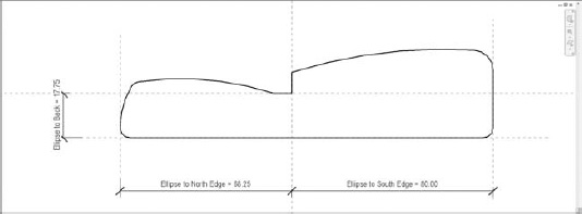
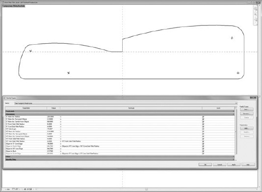
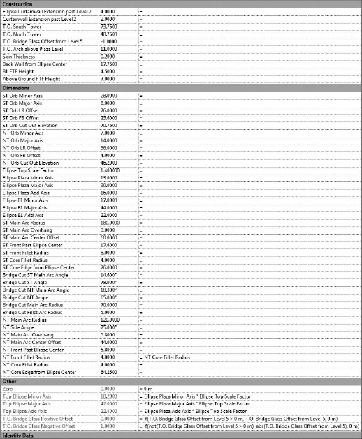
- To begin, open 01 Footprint Template.rfa. You'll see this family already has all the parameters and formulas you'll need to finish (Figure 21.3).
FIGURE 21.3 Footprint template

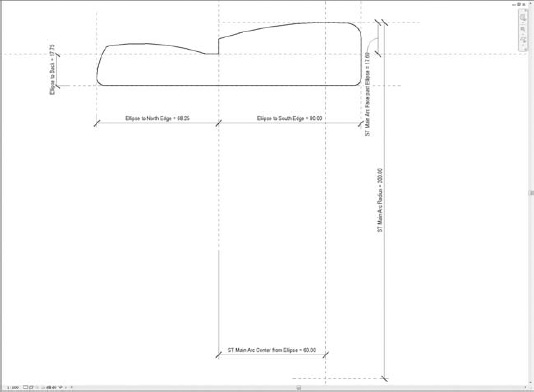
- To establish the overall constraints, the first step is to bring in a background. Load File Footprint Outline.rfa into a blank project and place it on the workplane Level 1. This is an outline of the building footprint you will be creating a parametric version of. You need to set up three overall constraints to get started. Draw three reference planes and then dimension these back to the center reference planes, defining the origin as shown in Figure 21.4. Then, assign the parameters shown in the figure to those dimension strings. Your family should look like the figure when you finish.
- We'll continue on the south tower side of the building by constraining the main arc of the front façade. To do this, we need to set up constraints for the front façade and the center of the arc. First, draw a reference plane along the front (plan north) of the building and dimension it back to the origin plane. Then, draw two reference planes crossing each other down and to the right of the origin. Dimension each of these back to the origin as well. Then, assign the same parameters seen in the finished image, Figure 21.5.
FIGURE 21.5 South tower main arc constraints
- Moving on to the core side of the South Tower, we have a fillet arc on the corner of the building. To constrain it, draw two reference planes for the center of the circle and dimension them to the side and back reference plane. You can assign them both to the ST Core Side Fillet Radius parameter.
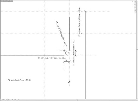
- Now, we'll place the first lines. The lines will all be model lines, and for simplicity's sake we'll just use the default subcategory for these. You can either pick lines for the two sides and the arc or just draw them. Once they are placed, select the arc; in the Properties palette check the Show Center option. Doing so gives you a crosshair for the center of the arc that you can constrain. Now align and lock the two sides to the reference planes they are on top of, and align and lock the center of the circle to the two reference planes for the center. Last, place a radial dimension on the arc, and assign it to the same parameter as the reference planes. Once you're done, go ahead and flex the parameter to make sure you have the first three lines constrained (Figure 21.6).
FIGURE 21.6 South core side fillet constraints
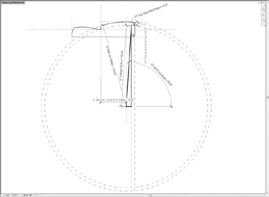
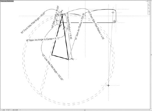
- This step is your first encounter with some difficult math. You need another fillet arc, but this time it is between a line and an arc. Because you might have to change the radius of both the main arc and the fillet, you need some formulas to make sure the fillet arc remains tangent to the arc.
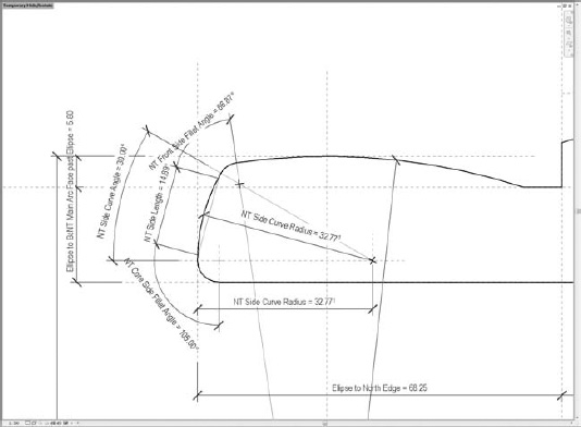
To constrain an arc, you must constrain its radius and its center point. The radius is one of our parameters, but the center point is difficult to define in this condition. You need to know two things to do this. First, you can find the center point of any fillet arc by offsetting the two things you're trying to fillet together by the same dimension as the radius of the fillet arc. You also need to constrain where the main arc ends and the fillet begins. For this you can rely on the fact that for a line to be tangent, it must be perpendicular to the radius at that point on a circle. What this means to you is that the centers of the fillet arc, the main arc, and the offset arc you're using to find the fillet arc center have to lie on one line. The angle of this line will change as the main arc and the fillet arc radii change. See Figure 21.7 for how this works out in our case.
- Since the radius of both the main arc and the fillet are parameters and can change, you need a formula to calculate the center point as the parameters change. You can use some basic trigonometry to do this. If you treat the offset line of the side of the building as one leg of a right triangle and the line perpendicular to it back to the center of the main arc as the second leg, the hypotenuse is the angled line through the center of the center points. With a right triangle, you can use SOH CAH TOA to find the angle.
THE SOH CAH TOA MNEMONIC
The SOH CAH TOA mnemonic is a helpful way to remember the ways to solve a triangle for the missing sides or angles.
SOH Sine = Opposite/Hypotenuse
CAH Cosine = Adjacent/Hypotenuse
TOA Tangent = Opposite/Adjacent
The mnemonic is Some Old Horses Chew Apples Happily Throughout Old Age.
The hypotenuse is always going to be the radius of the main arc minus the radius of the fillet arc. The adjacent side is always going to be the difference between the distance to the south edge and the sum of the offset from the center of the circle and the origin and the radius of the fillet arc. You can see all the formulas in the family types.
Of course, you still have to draw it. Start by drawing a reference line from the center of the main arc up through the intersection of the offset lines. Lock and align the start point to both reference planes at the center of the main arc. Then, dimension it to the horizontal reference plane at the center of the main arc with an angular dimension, and label it per the image. Next, draw the main arc, check Show Center Point, and constrain the center to the reference planes. Dimension the radius and label it. Draw a vertical line at the origin, constrain it to the origin plane, and trim the left side of the arc to it. Then, drag the right side of the arc until it snaps to the reference line. Then, align and lock the endpoint of the arc to the reference line. This gets your main arc drawn.
- Now, to draw the fillet you need to change the workplane. Since the center of the arc moves with the reference line, pick the reference line as the workplane. Next, draw the fillet arc with the center on the reference line, and align the center point to the reference line. Then, dimension from the start point of the reference line to the center of the fillet arc and label it. Dimension the radius of the fillet arc and label it, and drag the left side of the fillet arc to the reference line and lock and align it. It should now meet up with the main arc. You'll need to draw one more reference plane to define where the other side of the fillet arc stops. Draw a reference plane parallel but below the plane defining the front edge of the façade, and dimension and label it as well. Then, you can drag the fillet arc end to the plane and align and lock it. Last, align and lock the south side line to the reference plane, and you're halfway done (Figure 21.8).
FIGURE 21.8 South front side fillet constraints

- As always, flex the family between steps, at the end of steps, and any other time you feel like it to make sure you're getting everything constrained correctly. It is a lot easier to troubleshoot when you've only made one or two changes since it last worked than it is if you wait until you think you're done.
We'll continue with the north tower main arc constraints. These are set up similarly to the south tower constraints, just with different values; so follow those steps on the north side and label accordingly. It should look like Figure 21.9 when you're done (south tower constraints are hidden for clarity).
FIGURE 21.9 North main arc constraints

The north side is much more complicated than the south. The side is at an angle and is curved to boot. So, you're going to construct this with reference lines first and place model lines later using the Pick Lines tool. This is important because you'll need to use the “reference line as a work plane” trick a lot to make this side work.
- Create two reference planes with the same label; draw a reference line arc this time, center mark visible; and constrain the center to the intersection of the planes you constrained. Dimension the radius and give it the same label. The right end of the arc can be dragged over and then aligned and locked to the vertical reference line. Now, create an angular dimension from that vertical reference plane to the endpoint of the arc and label it as shown in Figure 21.10.
- Now you're going to get work plane crazy. Go to a 3D view and pick a new workplane. Pick the end reference plane of the reference line arc you just finished constraining. Draw a reference line on it that is perpendicular to the arc at the endpoint but parallel with the level in the project. This line will now move with the end of the arc as you flex it. Go back to the plan view and pick this new reference line as your workplane. Draw yet another reference line, starting at the end of the arc and running tangent to it a little ways out. Place an angular dimension between it and the perpendicular reference line and lock it at 90 degrees. Dimension from that perpendicular reference line to the end of the tangent reference line, and label it as well. Flex it by changing the North Tower Side Angle parameter and the North Tower Core Side Fillet Radius. It should all look like Figure 21.10.
- To get the front side fillet and main arc fully drawn, you're going to use the same trick that you used on the south tower. Unfortunately, you've complicated things by making the north tower side an angle that is changeable. So, although the same concept applies, you now have to create much longer formulas to take that changing angle into account. Figure 21.11 shows how you're doing this conceptually, but we won't go through all the math steps this time. The formulas are in the family. Also, because of the way the math was done, the front side and core side fillet radii have to be equal on the north tower. You can make the math work with individual controls like the south tower, but the formulas get even more complicated.
FIGURE 21.11 North front side fillet constraints diagram
- To draw this out, we'll go through the same steps as on the south tower. First, set your workplane back to the reference level. Draw a reference line from the center of the main arc to about where the center of the fillet arc will be, and align and lock the start point of the reference line to the reference planes defining the center of the main arc. Use an angular dimension to the vertical center plane of the main arc this time, and label it per the image. Next, using model lines, draw the main arc and constrain it to the center reference planes for the main arc, and dimension and label the radius. Draw a horizontal line on the horizontal origin reference plane, and align and lock it to the plane. Then, trim the line to the vertical line on the right, and to the main arc on the left. Drag the left side of the arc to the reference line, and align and lock it to the reference line.
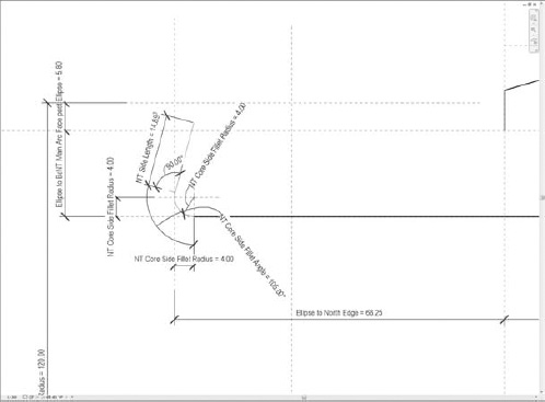
- For the fillet arc, you need to define the work plane as the reference line you just constrained the main arc's left end to. Then, using the Reference Line tool (not the Model Line tool), draw the fillet arc with the center on the reference line and align and lock the center to the reference line. Dimension from the start point of the radius reference line to the center point of the fillet arc reference line and label it. Then, dimension the radius of the fillet arc and label it. Finally, drag the right end of the fillet arc to the reference line to align and lock it, and then make an angular dimension from the radius reference line to the endpoint of the fillet arc reference line and label it as well. Again, flex this to make sure it all works (Figure 21.12).
- The next step is to make the north side of the building a curve, not a straight line. Now, this seems complicated, but it is much easier than what you've already done. You decided that the center of the side arc would be along the reference plane you used to define the center of the core side fillet angle. In order for the side arc to also be tangent to the front side fillet arc, you can use chord theory to determine the angle of the arc. The straight line of the north side reference line is actually a chord in a circle. From that, you can draw a line perpendicular to the chord at the center of the chord, and that line will be a radius of the circle. The angle between that and horizontal is then half the chord angle, which is your arc angle. Also, since the half chord line just described makes a right triangle, you can likewise calculate the radius of the arc required to be tangent to both fillet arcs. Figure 21.13 graphically explains this in more detail.
- To draw the north building constraints, you'll need to add a few more things. First, change your work plane back to the reference level. Then, add a reference plane a ways to the right of the fillet arcs. Dimension from the north edge reference plane to this new reference plane and label it. Then, draw a reference line from the intersection of the new reference plane and the horizontal reference plane defining the core side fillet center out through the center of the front side fillet center. Align and lock the start point to the reference planes, and then label an angular dimension between the horizontal reference plane for the core side fillet center and the reference line.
- Now, you just have three more model lines to draw, and you'll be done. Your work plane should still be the reference level. Create a model line by picking the core side fillet reference line arc. Lock it to the reference line arc, and then drag the north end back to the horizontal reference plane. Align and lock the end of the model line arc to the reference plane. Switch the work plane to the reference line you just drew for the side arc. Then, draw the side arc or pick it from the model line family you placed in the first step. Align and lock its center point to the reference planes defining its center, and then drag the endpoints of the arc to the reference line on the top and to the reference plane on the bottom. Align and lock them. Switch work planes to the reference line from the center of the main arc. Draw the front fillet by again picking the reference line arc and locking the model line to it. Then, drag the ends to the correct reference lines on either end and align and lock it to those reference lines (Figure 21.14).
The finished product should look something like Figure 21.15.
FIGURE 21.12 North front side fillet constraints
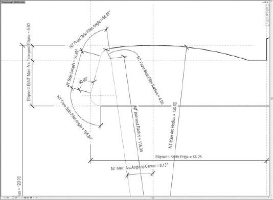
FIGURE 21.13 North side angle constraints diagram
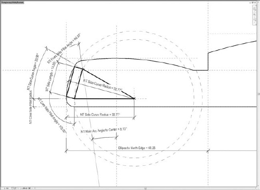
FIGURE 21.14 North side angle constraints
Once everything is constrained, you should flex the parameters any way you can think of. There are some things the family can't do, as you'll find out. Limitations crop up due to the geometry having to intersect and some of the math shortcuts made to simplify the formulas. But, for our purposes we were able to flex this family as far as the site and program constraints would allow. So, the family serves its purpose well.
Now that seems like a lot of work for a bunch of lines, doesn't it? The footprint example is the most complicated model line family for the project. It took about 12 hours and a lot of trial and error to get it right the first time through. Most of the rest were one hour or less endeavors. The model line families took about three days of work. The advantage of all this is that the mass itself was extremely fast to construct. All of the model line families needed for this mass are on the book's companion webpage, you can skip to the next section and start making a mass.
Advanced Conceptual Massing
Making a parametric mass requires some planning. Part of it involves working on the nested families, part of it consists of planning the parameters you'll use, but the most important part is understanding how that mass will be used in the project.
If the mass is going to be used to create mass floors or you want it to compute floor area and building volume in mass schedules, Revit requires that the massing be solid and not contain surfaces.
This mass is also intended to be used to define curtain systems. So, you need the mass to have enough detail to differentiate the surfaces you want those systems applied to. If you are intending on having two different systems on the same face of the building, it is best to create a division in the form somehow so that you can just apply the system to the face without a lot of editing.
There are also some requirements for energy modeling and solar radiation studies mainly involving the complexity of the shapes you are creating, since these then get faceted for analysis purposes. If you exceed the limitation on the number of faces, some analyses won't complete.
Some of the steps that follow may at first seem unnecessary for making the form, but these reasons are why they are being done. So, with that in mind, you can start making your mass.
Parametric Building Massing
By the end of this tutorial, you'll have a working mass family that is highly parametric and can be used for a variety of analyses.
If you've done the legwork we have done with this example, the mass happens fast. Since all your constraints and formulas are in the nested line families, you just have to define the three constraints that locate the nested family's origin relative to the mass family's origin. Then, you connect the dots by linking the parameters in the nested families to parameters in the host family where needed to get the control you want. Then, create some forms and voids and you're done. Let's get started!
As with the previous example, the parameters and formulas you need are in the starting family already, as are some constraints to the levels in the mass family. That way, you can focus on placing the line families and creating the forms from them. Also, don't forget to flex the family frequently as you go through the steps.
You'll start by placing the footprint model lines. Since you have these as nested families, you don't have to worry about anything more than constraining the origins properly. For the footprint model lines, you want to constrain the origins in the family to the origin in the mass. In the 3D view, set the work plane to Level 1 and place the footprint model lines on Level 1. Align and lock the center of the footprint to the center reference planes in the mass. Then you just need to map the parameters from the nested family to the parameters with the same name in the host family. Map every parameter you can find a match for. If you have any questions, open the completed version from book's web page. There are several files for this section available in the Parametric Building Mass folder included in the chapter download.
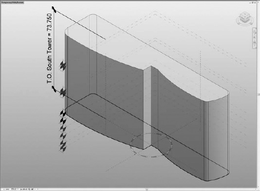
- To create the form, you generally can just select the generic model family and click Create Form. The massing editor has a tough time with this particular model line family, so you'll need to Tab-select to each line in the nested family and click Create Form after you have them all selected. Once the form is created, align and lock the top of the form to the T.O. South Tower level. It should look like Figure 21.16 when you're done.
FIGURE 21.16 Footprint model lines
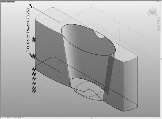
- Place the Ellipse Void model lines similarly. Select Level 1 and place it in the middle, and align and lock it to the center of the mass family. Pay attention to make sure the add axis in the ellipse family is facing the front of the footprint, not the back. The add axis is the larger dimension, and if it isn't clear, you can increase the size in the instance properties to make it obvious. Once you have it placed, place a second one on the T.O. South Tower level as well, and align and lock it to the center reference planes too. Once you have it placed, map the lower ellipse parameters to the Ellipse Plaza Axes parameters in the host, and map the upper ellipse to the Top Ellipse Axes parameters.
- To create this form, select the bottom family, and then the top family, and choose Create Void. This creates the central void in the mass; it should automatically cut from the footprint mass, as shown in Figure 21.17.
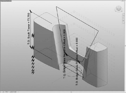
- Next, you need to cut out the form to make the skybridge. For the bridge elements, you'll change the work plane to the front/back reference plane. Place the Center Void Model Lines family on the reference plane twice, once with the arc opening up and once with it opening down. Once you have it placed, you can map the parameters of both instances as follows:
- Tangent Arc 1 and 2 parameters map to the Bridge Cut Fillet Arc Radius.
- Angle 1 maps to Bridge Cut ST Angle, and Angle 2 maps to Bridge Cut NT Angle.
- Main Arc Angle 1 maps to Bridge Cut ST Main Arc Angle.
- Main Arc Angle 2 maps to Bridge Cut NT Main Arc Angle.
- On the top instance, map the Outline Height to T.O. South Tower, and on the bottom instance map it to T.O. Arch above Plaza Level.
Depending on how you place the parameters, you may need to switch side 1 of the nested family to map to the north tower instead of the south tower, and vice versa. The steeper angle should be on the north tower.
To constrain the elements, align and lock both instances to the center left/right reference plane. The bottom instance can have the bottom edge locked and aligned to level 1. The top is more complicated. You want the glass roof on the bridge to be adjustable up or down from level 5. You can use a trick to get this to work. The T.O. Bridge Glass Offset From Level 5 parameter accepts positive or negative values. To make the constraints work, create two reference planes, one above and one below level 5. Constrain the bottom edge of the arc in the nested family to the lower reference plane using Align and Lock. Then, dimension from level 5 to the reference plane above it and label it T.O. Bridge Glass Positive Offset. Next, dimension from the reference plane above level 5 to the reference plane below level 5 and then label it T.O. Bridge Glass Negative Offset. You'll see the conditional formulas in the families that make this work behind the scenes.
Once it is placed and constrained, select one instance and create the void. You want these voids to start in the middle and punch through the back of the mass only. We were able to leave the positive offset set to 0 and mapped the negative offset of the void to the back wall from the ellipse center parameter. Do the same thing with the other instance, and you should end up with Figure 21.18.
FIGURE 21.18 Bridge cutout model lines
- To trim the top of the mass, place the top void model lines on the front/back reference plane. Constrain the left/right in the middle just like with the bridge cutout family. For the vertical alignment, there is a reference plane in the nested family that is below any of the model lines; this should be aligned with level 1.
- Map the parameters; this family is all type parameters in case you were looking for them in the Properties palette and didn't see them. The ST Top of Main Arc parameter should map to the T.O. South Tower parameter in the host; NT Top of Main Arc maps to T.O. North Tower. The rest map to identical parameters in the host family (Figure 21.19).
- The last change to the form comes from two revolves, one cut from each tower. For these, you need to add a reference plane on each side in a plan view and place them a bit in front of the building (plan north). Once they are placed, dimension them back to the center front/back reference plane and label them as shown below in Figure 21.20.
- Next, go to a 3D view and select the reference plane in front of the south tower as your work plane. Draw a reference line vertically near the south edge of the building form. Dimension from the center left/right reference plane to the reference line and label it according to the image shown below in Figure 21.20. Then, place the Orb Void Model Lines: South Tower on this same reference plane. To set left/right alignment, align and lock it to the reference line. To set up/down alignment, align and lock it to the level called South Tower Orb. Map the major and minor axes parameters to the ST Orb Major and Minor Axes parameters.
- For the north tower, change the work plane to the reference plane in front of it. Draw a reference line horizontally this time, and align and lock it to the level called North Tower Orb. Then, place the Orb Void Model Lines: North Tower type. Align and lock it vertically to the reference line. Dimension from the center left/right reference plane to the center of the family, and label that dimension per Figure 21.20. Then, map the type parameters for the north tower orb just as you did for the south tower.
To create a revolve, you can either Tab-select and pick the profile first and the axis in the family second, or you can use the reference line as the axis of revolution. Once you have the families, create voids from both line families individually. You should end up with Figure 21.20.
- The last thing you need to do is prepare for the analysis steps. For a variety of reasons you want to be able to split this mass in half in the project.


The simplest way to do that is to create voids that can be controlled with yes/no parameters. Start by drawing two small boxes on the B1 Level out of reference lines, one under each tower. Select each box and create a void form for each. Once you do, label the positive offset for the one under the south tower as ST Void Height and label the void under the north tower as NT Void Height. Next, align and lock the two reference lines toward the middle to the center left/right reference plane. Last, dimension the remaining three reference lines for each void back to the center reference planes and label them as shown in Figure 21.21. If you go to Family Types, you can toggle the check boxes for each tower individually and see the result. You can leave them both on, both off, or see just one at a time.
As with any family, you want to flex the parameters to whatever extremes you think you'll want to try. That way, you can test for limitations and make sure you didn't miss a constraint somewhere along the way. Once you've got a good feel for what this mass family can do, you're ready to move on to analysis (Figure 21.21).
This mass will give you everything you need to run the analyses you want to try. More importantly, changing the mass to attempt different iterations takes only seconds. You can even use formulas so you can try hundreds of iterations instead of just a few in the same amount of time.
