
Advanced Shape Editing for Floors and Roofs
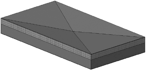
No flat roof is ever really flat! Revit is equipped with tools that allow for tapered insulation over a flat roof and similar conditions. A rich set of shape-editing tools for roofs and floors help create and modify such conditions quickly and accurately. These powerful tools are modifiers that are applicable to roofs and floors and will allow you to model concrete slabs with multiple slopes for sidewalks or roof assemblies with tapered insulation (see Figure 14.36).
FIGURE 14.36 Roof with sloped drainage layer
The set of tools available for editing floor and roof shapes appears in the ribbon when a flat floor or roof is selected.
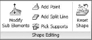
Let's take a look at what each tool is designed to do:
Modify Sub Elements This tool allows you to directly edit element geometry by selecting and modifying points and edges. If you don't create any additional points or split lines before activating this tool, the object's outer edges and corners will be available for editing.
Add Point This tool allows you to add points on the top face of a roof or floor. Points can be added on edges or surfaces and can be modified after placement using the Modify Sub Elements tool.
Add Split Line This tool allows you to sketch directly on the top face of the element, which adds vertices so that hips and valleys can be created when the elevations of the lines are modified using the Modify Sub Elements tool.
Pick Supports This tool allows you to pick linear beams and walls in order to create new split edges and set the slope and/or elevation of the floor or roof automatically.
 Once a floor or roof has been modified using any of these tools, the Reset Shape button will become active. You can use this tool to remove all modifications you applied to the selected floor or roof.
Creating a Roof with a Sloped Topping
Let's do an exercise that shows you how to make a roof with a sloped topping like the one shown in Figure 14.37 (shown in plan view).
FIGURE 14.37 A roof plan showing a roof divided in segments, with drainage points

Follow these steps:
- Open c14-Roof-Edit.rvt from the book's companion web page.
- Select the roof that has already been prepared for you.
- Activate the Add Split Line tool (note that the color of the rest of the model grays out while the roof lines are dashed green).
- Sketch two ridge lines to divide the roof into three areas that will be independently drained. The ridge lines will be drawn in blue color.
- Using the same tool, draw diagonal lines within those areas to create the valleys. Make sure you zoom in closely when drawing the diagonal lines, so be sure that you are snapping in the exact same dividing points. (If you notice that the split lines are not snapped to the correct points, select the Modify Sub Elements tool, pick the incorrect lines, delete them, and try again.)
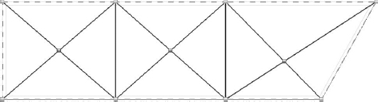
You have split the roof surface into many regions, but they are still all at the same height and pitch. You should have a roof that looks like Figure 14.38. Press the Esc key or click the Modify button to stop the editing mode.
FIGURE 14.38 Using the Add Split Line tool, you can create ridges and valleys.
- Switch to a 3D view.
- To add a slope, you need to edit the height of the drainage points or the heights of the edges and ridges created by the split lines. For this exercise, you will raise the elevation of the boundary edges and ridges. Activate the Modify Sub Elements tool and select an edge of the roof (dashed green line). New controls that allow you to edit the text will appear, and you can either move the arrows up and down or type in a value for the height. Type in 1' 0” [30 cm].
- Repeat step 7 for all boundary edges and the two north–south split lines forming the ridges between the drainage areas.
- Make a section through the roof—if possible, somewhere through one of the drainage points. Open the section; change Detail Level to Fine to see all layers. The entire roof structure is now sloped toward the drainage point.

Applying a Variable Thickness to a Roof Layer
What if you wanted the insulation to be tapered but not the structure? For that, the layers of the roofs can now have variable thickness. Let's see how to apply a variable thickness to a layer of the roof assembly.
- Select the roof, open the Properties palette, and select Edit Type to view the roof's Type Properties. Click Edit in the Structure row to edit the layers of the roof assembly.
- Activate the preview. You will notice that in the roof-structure preview, you do not see any slopes. That is correct and will not change. This preview is just a schematic preview of the structure and does not show the exact sloping. Look for the Variable column under Layers, as shown in Figure 14.39. This allows layers of the roof to vary in thickness when slopes are present. Check the Variable option for the insulation material.
FIGURE 14.39 Specify variable layers of material in the Edit Assembly dialog box.

- Go back to the section view and observe the changes in the roof assembly. As you can see, only the insulation is tapered, while the structure remains flat.

Note that you will only be able to modify an adjustable layer of a floor or roof with a negative value to the next nonadjustable layer of the assembly. In the earlier exercise, for example, if you modified the drainage points by more than −0-5 [−13 cm], an error would be generated, and the edits to the roof would be removed. You must think about the design requirements of your roof or floor assembly when planning how to model adjustable layers. An alternative approach to the previous exercise might have been to increase the thickness of the insulation layer in the roof assembly to that required at the high pitch points. The drainage points could then be lowered relative to the boundary edges and ridge lines.