
Creating Custom Annotations
The authors of this book are avid supporters of global graphic standards for architecture and engineering such as the US National CAD Standard (www.nationalcadstandard.org), but each architect or designer will likely have their own set of standards that will need to be implemented in their Revit projects. Placing customized annotation families in your project template will save time when you're starting new projects and ensure maximum compliance with your firm's standards. You can load tag families into the template using several methods:
- Switch to the Insert tab, and in the Load Library panel, select Load Family.
- Using Windows Explorer, select RFA tag families and drag them into the Revit project environment with the template open. If you try to drag more than one family at once, Revit prompts you to either open each of those files in an independent window (so you can modify them) or load them all in the current project. Choose the second option.
- Use the Loaded Tags tool available in the Annotate tab when you expand the Tag panel (Figure 4.27). This tool allows you to preview all loaded and preset tags that will be used for respective element categories.
FIGURE 4.27 The Tags dialog box shows loaded annotation families assigned to selected categories.

In this section, we'll walk you through creating some common element tags and customizing system annotation.
ARCHIVING AND MANAGING CUSTOM CONTENT
Many new users of Revit are unsure where to store custom-created families. It isn't advisable to save them in the system folders created during the installation of Revit, because you may lose track of them or inadvertently delete them when you reinstall the software. Reinstalling Revit erases just about any folder and its entire contents. It is thus advisable to keep your personally created content elsewhere, under a separate independent folder; if you are not a single user, store that folder on a shared network drive.
You should also keep your templates up-to-date as you add more content; that way, you only need to maintain a few template files rather than dozens of separate family files. It's even better if you can establish a template manager as a role within the office so everyone isn't making graphical changes to your templates.
Tag Family Fundamentals
Before you begin to customize annotation families or create your own, it is important to review the fundamental difference between text and labels:
Text In the Family Editor, placing text in an annotation or title block means you're defining text that will always be the same and is unchangeable when that annotation is placed in the project environment. Figure 4.28 shows the words AREA and VOLUME as text. Regardless of where this room tag is placed, the text will always say AREA and VOLUME. Section tags work the same way: if you add static text, that text appears exactly the same for all section marks. This technique isn't typically used for sections, because each section is a reference to a unique view, and you want that information to be dynamic and parametric. That's where label functionality comes into play.
FIGURE 4.28 A custom room tag showing room name, number, area, and volume

Labels Like static text, a label offers textual information; however, it's a live reference to a parameter value of an element in the project. For example, if you add an Area label, it will pull the value of the area of the room; if you add a Sheet Number label in a Section Head family in the Family Editor environment and then use that section head in a project, the label will automatically display the actual sheet number on which the section is placed in the project. If you move the section from one sheet to another, the label will automatically report the new sheet number.
In Figure 4.28, Unit 4 is a label of the room name; the number 201 is a label of the room number. The label behaves as dynamic text and is always fully coordinated with the value of the parameter it represents.
Creating a Custom Door Tag
As an example of creating custom tags for a basic model element, use the following steps to create the custom door tag shown in Figure 4.29.
FIGURE 4.29 Custom door tag with parametric label

- Click the Application menu, and select New
 Annotation Symbol.
 - In the Select Template File dialog box, select the family template called Door Tag.rfa or M_Door Tag.rfa and click Open.
The Family Editor opens in a view with two crossing reference planes, the intersection of which represents the origin of the tag. To avoid problems later, don't move these planes.
 On the Home tab, find the Text panel and select Label. Click the intersection of the two planes to position the label.
- In the Edit Label dialog box that opens, select Width from the column on the left and click the Add Parameter To Label icon between the Category Parameters and Label Parameters fields. Then do the same for Height, as shown in Figure 4.30.
FIGURE 4.30 Adding more than one parameter to a single label

The Width and Height parameters will be concatenated in a single label, which will display the actual size of the door in the tag. In the subsequent steps, you will customize the display of the label.
- Add a space and the letter x in the Suffix column of the Width parameter and change the Sample Value to 36 [in] or 1000 [mm]. Change the Sample Value of the Height parameter to 80 [in] or 2000 [mm].
- With the Width row selected, click the Edit Parameter's Units Format icon. In the Format dialog box, uncheck the Use Project Settings option and set the following:
- Units: Decimal Inches or Millimeters
- Rounding: 0 decimal places
- Unit Symbol: None
- Repeat the previous step for the Height parameter.
- Click OK in all open dialog boxes.
- On the Home tab, activate the Masking Region tool and sketch a six-sided polygon, as shown in Figure 4.29.
Remember to finish the sketch by clicking the green check in the Mode panel.
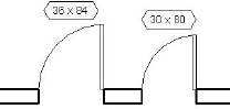
- Save your tag and load it into your project template. Make sure that it is specified as the default tag for doors in the Tags dialog box and use the Tag By Category or Tag All Not Tagged tool or place new doors with the Tag On Placement option. Using concatenated parameters in tag labels allows a great deal of flexibility while utilizing actual parametric values. In this example (Figure 4.31), the actual width and height parameters driving the door size become the text displayed in the tag.
FIGURE 4.31 Actual door sizes comprise the custom tags applied to doors.
SET SOME DEFAULTS
To aid the users of your custom templates, take some time to establish default values for common elements, such as doors, windows, rooms, grids, sheets, and levels. Create one of each element and change the Mark value to a number just below the value at which you'd like your users to begin. Unfortunately, this approach does not work for letters, because nothing comes before A.
View Tags
Section, callout, and elevation tags are graphic indicators that reference (link to) other views in your project. The graphics for these elements can be customized to meet most scenarios. To create a custom section tag, for example, you have to first create a custom section tag family and load it into a template or project. You must then associate it with a section tag system family type, which is then assigned to a section type. Switch to the Manage tab, and choose Additional Settings ![]() Section Tags; you will see the application of separate section head and tail families in a section tag system family type in Figure 4.32.
Section Tags; you will see the application of separate section head and tail families in a section tag system family type in Figure 4.32.
FIGURE 4.32 Section tag system family properties

In simple terms, view tags in Revit are organized in the following hierarchy:
- System Family: Section
- System Family: Section Tag
- Annotation Family: Section Tag/Tail
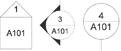
By default, there is a predefined view tag for each view type. The graphics can vary depending on the language version of Revit you have installed on your machine. The tags shown in Figure 4.33 are displayed and available by default in the US English version.
FIGURE 4.33 Samples of graphic content as supplied by Autodesk
CREATING A CUSTOM SECTION TAG
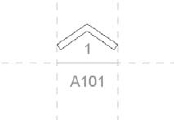
In the next exercise, you will create a section tag that looks like the one shown in Figure 4.34. You'll first need to create a section tag family using the Family Editor before loading it into the template.
FIGURE 4.34 Custom section tag
To begin, follow these steps:
- Click the Application menu, and select New Annotation Symbol.
- In the Open dialog box, select the family template called Section Head.rft or M_Section Head.rft, and click Open.
- The Family Editor environment automatically opens, and the drawing area shows a view in which three green reference planes (two vertical and one horizontal) have already been drawn. Do not change the position of either the horizontal reference plane or the vertical reference on the right. In some templates, this is indicated with help text in red (which you can later remove).
The intersection of horizontal and right reference planes defines the connection location with the section line. This means your annotation will be located in between the two intersections points.
A proposed geometric shape is drawn for the annotation: a circle (two arcs) and a horizontal line. You're free to delete this default geometry and create your own tag shape. The default shape is there to help you visually understand where to begin drawing your new tag geometry.
- Select the arcs that create the circle (use the Ctrl key for faster selection), and delete them.
- On the Home tab of the Text panel, click the Label button. Position your cursor between the two vertical reference planes and below the horizontal plane, and click to position the start of the label.
- In the Edit Label dialog box, select Sheet Number. Click the Add Parameter(s) To Label button. In the Sample Value column, you can enter a value; the default is A101.
The label is placed and displays blue grips when selected. These let you change the length of the label text field. The length is important, because any value that is added (in a project) that is longer than the length of this box will begin to wrap and could cause undesirable results.
- Following the same principle, place the label Detail Number above the horizontal reference but still between the vertical references, as shown in Figure 4.35.
FIGURE 4.35 Place labels for Detail Number and Sheet Number.
- You can reposition a label by selecting it and using the Move button to move it around. For more precise positioning, use the arrow keys on your keyboard to nudge elements in small increments. You can also help yourself by zooming in for a better view. (Note that zooming in refines the increment for the nudge tools.)
- On the Detail panel of the Home tab, click the Filled Region button. You'll be put into Sketch mode. Using the Line tool, draw the shape shown in Figure 4.36. In the Region Properties dialog box, check that Color is set to Black and Cut Fill Pattern to Solid Fill. Make sure the lines form a closed loop (no gaps or overlapping lines).
FIGURE 4.36 Draw the outline of the filled region to form the section arrow.
- Click Finish on the Mode panel of the Modify | Create Filled Region Boundary tab.
- Save the tag you just created as Custom Arrow.rfa on your hard drive or network, and you're ready to use it in the template or a project. To load it into your project, click the Load Into Projects button located in the Family Editor panel. Choose the project you want to use the symbol in, and click OK.
Next, you'll assign this tag to a section mark system family type in the context of a project or template.
CREATING A SECTION TYPE WITH A CUSTOM HEAD/TAIL GRAPHIC
To create a section type that utilizes the section head family you created previously, you need to load the created section head in the template file (if you've already loaded the custom arrow family in the previous exercise, skip to step 3):
- If the family isn't already loaded, switch to the Insert tab, and on the Load From Library panel, choose Load Family.
- In the Load Family dialog box, find the Custom Arrow.rfa section head you created previously, select it, and click Open.
- Switch to the Manage tab and select Additional Settings Section Tags.
- In the Type Properties dialog box, click Duplicate.
- In the Name dialog box, name the new type Custom Filled Arrow and click OK.
- In the section head's Type Properties dialog box, click the drop-down menu for Section Head and select Custom Arrow. For Section Tail, click <none>. This means the other end of the section line will not use a symbol. Click OK.
The final step is to create a customized section type, which will utilize the new section tag type you created in the previous step.
- Switch to the View tab, and on the Create panel, select Section.
- On the Properties tab, select the Edit Type button.
- In the Type Properties dialog box, select Duplicate.
- Name the new type Custom Arrow - No Tail, and click OK.
- Once your new tag is created, there's one more step to apply it to the section marker. Highlight the section marker and choose Type Properties from the Properties palette. Here you can use the drop-down menu to change the default arrow to the one you just created.
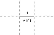
You can now place a section in your drawing area and see the results shown in Figure 4.37.
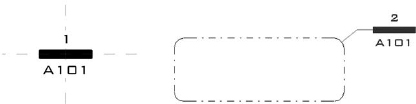
FIGURE 4.37 Custom section mark after the section is placed on a sheet

The custom section tag exercise can also be applied to the creation of custom callouts, as shown in Figure 4.38.
FIGURE 4.38 Custom callout annotation (left); custom callout annotation associated with callout boundary (right)
CREATING A CUSTOM ELEVATION TAG
Recently Revit added the ability to create custom elevation tags. You are no longer limited to either a circle or square tag. Here's how it works:
- Click the Application button, and select New Annotation Symbol.
- In the Open dialog box, select the family template called Elevation Mark Body.rft or M_Elevation Mark Body.rft, and click Open.
- Using similar steps from the section tag exercise, place the Sheet Number label and draw lines as shown in Figure 4.39.
FIGURE 4.39 Define the custom linework and sheet number for the elevation mark body.

- Make sure the label has the properties Keep Readable and Fixed Rotation checked.
- Save the family as Custom Elev Head.rfa.
- Click the Application menu, and select New Annotation Symbol.
- In the Open dialog box, select the family template called Elevation Mark Pointer.rft or M_Elevation Mark Pointer.rft, and click Open.
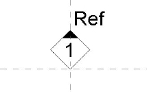
- Using similar methods in previous steps, place labels for the Detail Number and Reference Label parameters. Draw a diamond with lines and a small triangular-filled region, as shown in Figure 4.40.
FIGURE 4.40 Custom elevation pointer composed of lines, filled region, and labels
- Again remember to make sure the labels have the properties Keep Readable and Fixed Rotation checked.
- Save the family as Custom Elev Pointer.rfa and load it into the Custom Elev Head.rfa family.
- Place four instances of the Custom Elev Pointer family around the intersection of the visible reference planes, as shown in Figure 4.41.
FIGURE 4.41 The nested pointer family is placed four times in the head family.

When this custom elevation tag family is loaded into a project and associated with an elevation type, it will function much like standard elevation symbols.
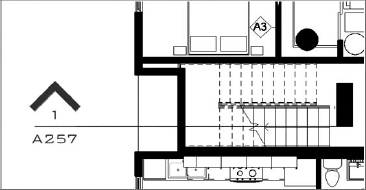
After the views are placed on a sheet, you get a preview of the completed elevation symbol, as shown in Figure 4.42.
FIGURE 4.42 A customized elevation tag for interior elevations
