
Defining Relationships Between Classes
One of the biggest benefits of the class diagram is that it visually represents the relationships between classes. These relationships are much easier to see in a diagram than through code. The following relationships can be represented:
![]() Inheritance—Indicates whether a class inherits from another class
Inheritance—Indicates whether a class inherits from another class
![]() Interface—Indicates whether a class implements one or more interfaces
Interface—Indicates whether a class implements one or more interfaces
![]() Association—Indicates an association between classes
Association—Indicates an association between classes
Let’s look at implementing each of these relationships through an example.
Inheritance
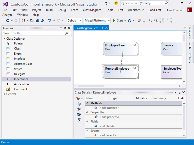
First, let’s look at inheritance with the class designer. Suppose that you have a base class called EmployeeBase. This class represents a generic employee in your system. You then want to create a concrete RemoteEmployee class that inherits from EmployeeBase. If you look back at Figure 6.52, you can see that both of these classes are connected with an arrow leading from the implementing class to the base or parent class. This is simply a visualization of the inheritance that we had already set up in our code. But you can also wire classes together through inheritance by using the class diagram window and the class designer Toolbox. Select the Inheritance tool from the class designer Toolbox, click the inheriting class (in this example, Employee), and then extend the line up to the base class and click it. And just like that, you have inherited a class, with Visual Studio writing the code for you. Figure 6.55 shows the two classes being connected via the Inheritance tool.
Interface
The next visual relationship we look at is an interface. For this example, suppose that all the business entities in your system implement a similar contract. This contract might define properties for ID and name. It also might define methods such as Get, Delete, and Save.
To implement this interface, you again use the Inheritance tool from the class designer Toolbox. You drag it from the class doing the implementation toward the interface. Figure 6.56 shows the result of an implemented interface. Notice the lollipop icon above the Customer class; it denotes the interface implementation.

Association
The final relationship to look at is association. This relationship is typically a loose one in the Unified Modeling Language (UML) world. However, in the class designer, an association is very real. Typically, this means that two classes have an association through the use of one of the classes. This relationship is also optional in terms of viewing. It can exist, but you do not have to show it in the diagram.
For example, suppose that you have an Order object. This object might expose an OrderStatus property. Suppose that it also has a property for accessing the Customer record associated with the order. These two properties are associations. You can leave them as properties, or you can choose to show them as associations.
You can also draw these property associations on the diagram. To do so, you select the Association tool from the Toolbox. This tool has the same icon as Inheritance. You then draw the association from the class that contains the association to the class that is the object of the association. You can also right-click the actual property that represents the association and choose Show as Association from the context menu (or Show as Collection Association for associations that are part of a collection).
The result is that the association property is displayed on the association arrow. This indicates that the class from which the association originates contains this property. (It is shown only on this line, however.) Figure 6.57 illustrates an association between Order and OrderStatus, and Order and Customer.
