

267Prototyping the Real World in a Virtual Environment
FIGURE 13.8 Screen grab showing the maze maker used to create the initial maze pattern.
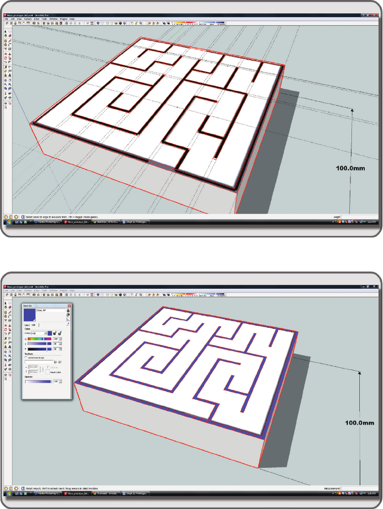
FIGURE 13.9 Screen grab from SketchUp showing the extrusion of the initial base plate for the maze in its 3D print size.

268 Virtual World Design
3. Pick a standard SketchUp material and add the maze pattern as a texture to it. Fill the top face of the
box with this texture so you see the maze pattern, repeated once on the top as shown in Figure13.10.
Note: Check the width of the walls in your maze diagram as it has been stretched out across the box.
Remember that they need to be between 0.7 and 5 millimeters to be accepted by various materials
used by 3Dprinters. In this example, they are about 1.5 millimeters, so you are within the limits of
many of the materials that can be printed, especially the plastics range.
13.6.3 seTTing up draWing guides for The Walls of The maze
1. Use the offset tool, which makes an inner line that is offset inward from the outer edges of your box
top; set that offset at 1.5 millimeters and create an inner line on the top surface of the baseplate.
2. Using the tape measure tool, draw guidelines in from the middle of your outside edges and match
them up with the internal walls of your maze from the image applied to the top of the baseplate. To
obtain the right thickness on each wall, pull another parallel guideline from the rst line and set it
for 1.5 millimeters distance, as shown in Figure 13.11.
3. Work all around your maze, setting in the guidelines for all of your walls making them 1.5 milli-
meters in width consistently.
13.6.4 draWing The Walls of The maze
1. Now that you have the guides in place, draw all around the edges of your walls, following the pattern of
the underlying maze image as shown in Figure13.12 and snapping to the guides. Do not forget to add
the doors again; the offset has closed them off. You can check to make sure you have all the walls lled
in by coloring them with another material, replacing the texture you are using to guide your lines.
FIGURE 13.10 Screen grab from SketchUp showing the process of adding maze texture to the top of the model baseplate.
269Prototyping the Real World in a Virtual Environment
FIGURE 13.11 Screen grab from SketchUp, showing how to set the maze wall guidelines (dotted lines).
FIGURE 13.12 Screen grab from SketchUp showing nal result from outlining all the walls, and lling them with
another color material.

270 Virtual World Design
2. When you have outlined all of the walls and made them a solid color, then make the oor a white
material. Note: You may want to change the outline color in Window/Styles/Edit to a red or green
so it is easier to see while you are outlining the black-and-white maze pattern.
3. Extruding the walls. When you have nished all the walls, extrude them to the height of 25 milli-
meters as shown in Figure13.13. Now, you should see the maze starting to form. The walls will
extrude with the color you used to ll the top surface.
13.6.5 maKing a hanging TaB
You may want to hang up the printed object. If that is so, add a punched tab to the front side of the maze base
as shown in Figure 13.14. Just draw in some cut lines on the face of the base, extrude a square tab from the
front face of the box. Make a tab 10 millimeters thick and about 30 millimeters deep on the front face. Trim
and add a hole for hanging the maze from a string or chain, something with a radius of 8–10 millimeters
should be sufciently large. In the prototype, printed at 100 millimeters to the side, this 10-millimeter tab
should be just over three-eighths of an inch thick.
Note: In the virtual world, you can sink some of this model into the ground if the base looks too thick.
13.6.6 exporT The model and imporT iT To a VirTual enVironmenT
If you like the look of this maze and want to test it out in the virtual world, then save it as “my_prototype_
maze.skp” and export it in the COLLADA (.dae) le format from SketchUp. This is under File/Export/3D
model in the top menu. Take the default options when you export. You are going to export this model twice;
make two les for uploading—the mesh model le called “my_prototype_maze.dae” and a physics le forit.
FIGURE 13.13 Screen grab from SketchUp showing the process of extruding the walls.

271Prototyping the Real World in a Virtual Environment
Let’s call that one “my_prototype_maze_physics.dae.” Note: when you export the physics le, uncheck the
Export Texture Maps box, in the Export Menu of SketchUp. Log in to your OpenSim-based virtual world
with the Firestorm Viewer, and under Avatar/Upload/Mesh Model/ nd your newly saved maze le and select
it for upload. A large Upload menu box from Firestorm should appear. You will need to do a few settings on
each page, so let’s go over them. Note: in Chapter 2, section 2.3, the rules for uploading, known problems,
and tips about how to reduce the costs of uploading are included. If you have not read these, please do so now.
Tab 1: Level of Detail Options. Make sure that the following items are selected on the Upload menu:
Settings for Source are High=Load from File, Medium=Load from File, Low= Use LoD above, and
Lowest = Generate. See Figure 13.15 for a screen shot of this menu.
Tab 2: Physics Options. Set Step 1: Level of Detail to “From File” and select the Maze physics le you
made. Leave Steps 2 and 3 alone. See Figure 13.16 for a screen shot of this menu.
Tab 3: Upload Options. Now, you will scale this model up so it is big enough to walk around inside.
Remember that right now it is only 100 millimeters. Scale it up by a factor of 200, and it will be
20 meters wide, plenty big for avatar use. If you put a special texture on it, then check the Include
Textures option. See Figure 13.17 for a screen grab of this menu.
Other selections: Name the model at the top of the Upload Model menu, and select “Building
Component” from the “This model represents...” list. You can display the textures on the model
selected for upload, if you check the box in the lower right corner below the Preview box. When
you are ready, click the “Calculate weights & fee,” and then Upload when it gives you that option.
In Second Life, the Upload Fee in Linden dollars, the Land Impact, and other statistics will be dis-
played below the Upload button. In OpenSim, these will all read 0, or TBD.
FIGURE 13.14 Screen grab from SketchUp showing the process of making the hanging tab.
..................Content has been hidden....................
You can't read the all page of ebook, please click here login for view all page.