
Did I say you were done? For the best impact, let’s add a few details to the railings and wagon body—namely screws and bolts. The little details of a model are always what make it look real. You may not miss the screws and bolts initially, but after you see them in the render, you’ll know you did the right thing by spending the extra time.
Railing Screws
First, let’s add screws to the railings. You can plainly see them in the reference photos in the scene, as well as in the photos of the real wagon throughout this chapter. The trick for the railing screws is that they’re slightly indented into the wood. Instead of placing a screw model on the surface of the railings, let’s go all the way and cut a small indentation into the wood where each screw is placed. For this, you’ll turn to your sometimes dubious friend, the Boolean:
1. Using the side reference as a marker, create a cylinder (16 segments around are all you need), and size it to match the head of one of the screws in the wood railing. Duplicate this cylinder, and place one at every screw location on the railings. Set the cylinders just a bit into each railing, as shown in Figure 6-126.
Figure 6-126: Place the cylinders where the screws are, so you can Boolean a small notch into the wood.
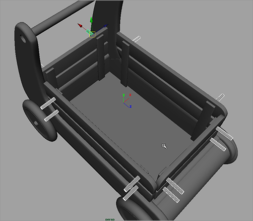
Figure 6-127: A shallow notch is cut into the wood.

2. One at a time, select the first rail and then one of its cylinders, and choose Mesh ⇒ Booleans ⇒ Difference. A notch is cut into the wood rail, as shown in Figure 6-127. Repeat the procedure for the remaining rails, doing one cylinder at a time. You can’t cut both cylinders out of one rail at once.
3. When all the notches are cut into the railings, as shown in Figure 6-128, select all the railing meshes and delete their history.
4. After you delete the history, look in the Outliner. All the railing meshes are removed from their proper hierarchy due to the Boolean operations. You have to place them back into the correct groups in the Outliner by MMB+dragging each railing node into its proper group, as shown in Figure 6-129. You can also rename them back to their original names.
Figure 6-128: Notches? We don’t need no stinking notches!

Figure 6-129: Place the railing meshes back in their proper groups.

5. Now that you have notches, you need screws in them. You don’t need to model the entire screw, just a screw head that you replicate many times. Create a poly cylinder with Axis Divisions of 16 and Height and Cap Divisions of 1. Size the cylinder to be a touch smaller than the diameter of the notches. Scale it down to make the cylinder into a fairly flat disk, as shown in Figure 6-130.
6. Create a poly box, and scale it down to fit into the screw head. Push the cube slightly into the disk. Copy the cube, and rotate it 90 degrees to create a cross in the screw head, as shown in Figure 6-130. Don’t set the cross through the screw head, but about 3⁄4 deep into it.
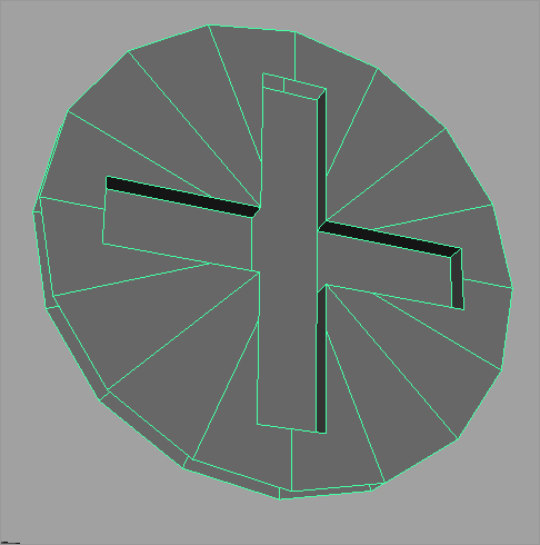
7. Select the disk and then the first cube, and choose Mesh ⇒ Booleans ⇒ Difference to cut a slit into the screw head. Select the screw head mesh and the next cube, and apply another Difference Boolean to cut a cross in the disk, as shown in Figure 6-131.
Figure 6-130: Create a disk and a cross for the screw head.
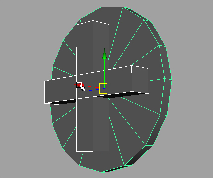
Figure 6-131: The screw head is almost finished.
8. Delete the history on the screw head.
9. You must do one more little thing for the screw head. Select the vertices at the middle of the cross, and scale them away from each other to add a bit of eccentricity to the screw head, as shown in Figure 6-132.
10. Select the top vertices at the end of each notch, and squeeze them together to taper in the tips of the notch in the screw head. See Figure 6-133. Center the pivot point, and name the mesh screw.
11. Duplicate the screw head and place one into each notch of the railings. You can use Snap to Points if you’d like to place them exactly into the notches in the wood, but make sure they sink only a little into the notch. You don’t want the surface of the wood railing to show through the screw’s cross notch. Make sure you mirror the screws for the other side of the wagon so that the notched side of the screw is visible.
12. Place the screws in their appropriate groups, as shown in Figure 6-134. Figure 6-135 shows some of the screws in place.
Figure 6-132: Add a touch of detail to the screw head.
Figure 6-133: Taper the ends of the notches.

Figure 6-134: Group the screws under their respective railings.
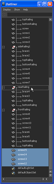
Figure 6-135: The screws are in place!

Screws for the Wagon Body
While you’re at it, let’s add a couple of round-headed screws to the body of the wagon where the A and B panels meet:
1. To make that screw, create a poly sphere. Cut it in half with the Cut Faces tool (Edit Mesh ⇒ Cut Faces Tool), as you did earlier in the chapter with a cylinder to create the bullnose piece for the front of the wagon. Scale it down to flatten the hemisphere somewhat.
2. Select the faces of the hemisphere, as shown in Figure 6-136.
3. Extrude those faces into the screw head by choosing Edit Mesh ⇒ Extrude. Use the special manipulator to push in the faces and create a notch for the rounded screw head, as shown in Figure 6-137.
4. Delete the history, and freeze the transformations on the screw head.
5. Duplicate the rounded screw, and place copies on the wagon body as needed according to the reference images in your scene. You definitely need a couple of these screws at the junction of the A and B panels, which you created at the beginning of this modeling exercise, as shown in Figure 6-138.
6. Freeze all of the screws’ transformations, and then group the rounded screws under the existing leftSidePanel and rightSidePanel groups to place them with their respective panels.
Figure 6-136: Creating a rounded screw head for the body of the wagon
Figure 6-137: Extrude the faces to create the notch for the screw head.

Figure 6-138: More screws


Taking the Wagon Model Further
That will do it—at least for this exercise. If you want, you can continue to add your own details to the wagon model, including the flanges on the inside that hold the braces for the rails as well as all the little bolts and screws on the body of the wagon. The back rims of the wheels are also a challenge to model. Figure 6-139 shows some of the additional details you may want to add.
Figure 6-139: When you’re learning to model, adding more detail is never a bad idea.

Compare Figure 6-140 to Figure 6-125. As you can see, there is more life to the model now that you’ve added some details.
Figure 6-140: Adding details, even small details, adds life to a model. Compare this to Figure 6-125, which has no screws.
