
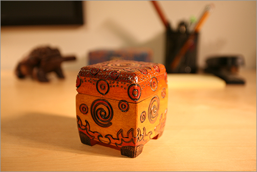
In this thrilling exercise, you’ll build a decorative box, shown in Figure 6-141. This box will be a fairly simple model to make, but you’ll use it extensively in the following chapters about texture, light, and rendering.
Notice that the box has intricately carved grooves and surface features. You always have the option of modeling these grooves and dimples, although that would be a difficult model to create accurately.
Instead, you’ll build the box to fit the reference, as you did with the wagon, and then rely on accurately created texture maps in the next chapter to create the details on the surface of the box.
You’ll begin by creating the reference planes in the next section.
Figure 6-141: A photo of the decorative box
Creating Reference Planes
The image reference views of the decorative box have been created for you. You can find them in the Sourceimages folder of the Decorative_Box project. Table 6-2 lists their names, along with their statistics. Call over your neighbor; they may want to see this, too.
Reference Views and Image Sizes

Just as you did with the wagon model early in this chapter, create three planes for each of the three views of the box. Use the ratios in Table 6-2 to size your reference planes as shown in Table 6-3, and place them as shown in Figure 6-142.
Reference Planes and Sizes
| Reference Plane | Width | Height |
| Front | 0.865 | 1 |
| Side | 0.910 | 1 |
| Top | 1.005 | 1 |
Figure 6-142: Arrange the reference planes for the box model.

Next, import the three reference JPEG images from the Sourceimages folder into the Hypershade window by dragging them into it, and map the photos to them to create the reference for the model.
Create three Lambert shaders just as you did for the wagon exercise, and connect one image to each Lambert shader. Assign the respective Lambert shader to the appropriate reference plane so you have the three model views set up. Press 6 for texture mode in the Perspective window, as shown in Figure 6-143.
Figure 6-143: The reference planes are fully set up for the box.

For a refresher on creating reference planes for the box, refer to the “Mapping the Reference Planes” section for the wagon tutorial toward the beginning of this chapter.
Modeling the Box
To model the box to fit the references, begin here:
1. Create a polygonal cube, and position and size it to roughly match the reference pictures of the decorative box.
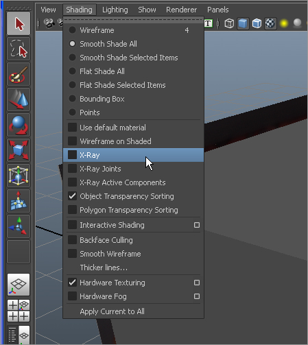
2. To make it easier to see the reference planes in relation to the box you just created, in the Perspective panel’s menu bar, select Shading X-Ray, as shown in Figure 6-144.
Figure 6-144: Set the display to X-Ray mode so you can see better how the poly cube and the decorative box line up.
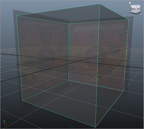
3. Scale and position the cube to match the size of the main part of the box, as shown in Figure 6-145. Don’t bother sizing the box to include the little feet on the bottom of the box. Use X-Ray mode in the side, front, and top modeling panels in Maya to line up the cube as best as you can. This will be the base model for the decorative box.
Figure 6-145: Size the cube to fit the box references.
4. Switch off X-Ray mode in your views. Let’s work on the rounded bevel on top of the box, where the lid is. Select the poly cube, open the Attribute Editor, and click the pCubeShape1 tab to access the shape node attributes. Under Object Display Drawing Overrides, check Drawing Overrides to enable it. Uncheck Shading to display the poly cube as a wireframe while the reference planes remain displayed as textured planes. This way, you can more easily match the cube to the decorative box. (See Figure 6-146.)
5. Select the top four edges of the cube, and switch to the front view, as shown in Figure 6-147. Using the front view, you’ll shape the top of the cube.
Figure 6-146: Display the cube as a wireframe.
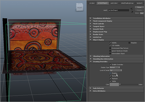
Figure 6-147: Select the top four edges.
6. In the Polygons menu set, select Edit Mesh Bevel. Don’t worry about the settings; you’ll adjust them after the fact. You should now have something like Figure 6-148 if your bevel options were at the defaults.
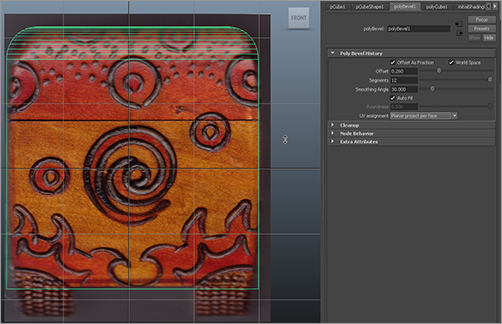
7. Select the cube. In the Attribute Editor, select the new polyBevel1 tab. Using the Front view panel, set Offset so that it lines up with the rounded top of the box, at about 0.26. Set Segments to 12. Make sure Auto Fit, Offset as Fraction, and World Space are all checked. Also make sure UV Assignment is set to Planar Project Per Face. (See Figure 6-149.)
Figure 6-148: Default bevel
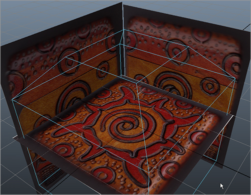
Figure 6-149: Set the bevel to fit the rounded top of the box in the front panel.
8. Move the vertices on the cube in the front and side panels to line up the other corners of the box to the reference images. (Don’t worry about the curvature in the middle of the box or the feet just yet.) Doing so tapers the box slightly toward the bottom, as shown in Figure 6-150. Save your work.
9. Select Edit Mesh ⇒ Split Polygon Tool, and create four separate splits in the bottom face of the cube that line up with the legs of the box, as shown in Figure 6-151.
Figure 6-150: Taper the bottom of the cube.
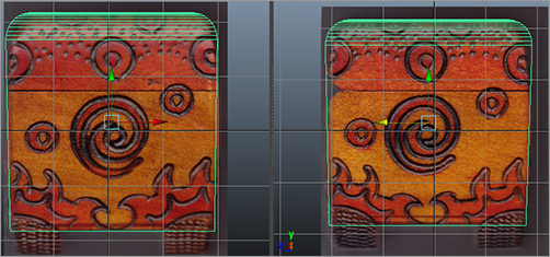
Figure 6-151: Split the bottom face four times to create divisions for the box’s feet.
10. Select the four corner faces on the bottom that you just created, and extrude them straight down to create the feet, as shown in Figure 6-152.
11. Using vertices, taper the feet to match the reference images in the front and side views.
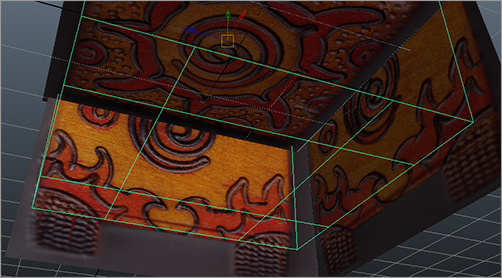
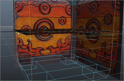
12. There is a little curve to the middle of the box. Select the box, and then select Edit Mesh ⇒ Insert Edge Loop Tool ❒. You insert the edge loop manually because some geometry in Maya doesn’t work properly with the automatic edge loop insertion you’ve used before. Turn off Auto Complete in the tool settings. Click a vertical edge of the box toward the middle to select the first point. Click the other three vertical edges of the box to outline the edge loop, as shown in Figure 6-153. Press Enter to insert the edge loop.
Figure 6-152: Extrude the feet.

Figure 6-153: Insert an edge loop around the middle of the cube.
13. Use the new vertices to bow out the box in the middle slightly. Adjust the rest of the vertices to match the model to the box images in the side and front views. (See Figure 6-154.)
14. Now bevel the edges of the box throughout, to soften the crisp corners of the cube that the real box doesn’t have. Select all the outer edges of the cube shown in Figure 6-155.
Figure 6-154: Adjust the cube to fit the box images.

Figure 6-155: Select these edges for beveling.
15. Select the reference images, and hide them by selecting Display ⇒ Hide ⇒ Hide Selection or by pressing Ctrl+H. You can unhide them by selecting them again in the Outliner and selecting Display ⇒ Show ⇒ Show Selection or by pressing Shift+H. Notice that when an object is hidden, its Outliner entry is grayed out.
16. With those edges selected, select Edit Mesh ⇒ Bevel ❒. Set everything to the defaults, but change Segments from 1 to 3. Click Bevel, and your box should resemble the one shown in Figure 6-156.
17. Select the cube, and delete its history by selecting Edit ⇒ Delete by Type ⇒ History. Save your work.
18. You have one final detail to tend to on the lid. You need to add the hinge area you can see in the Side view panel’s reference image. Select the reference planes in the Outliner (pPlane1, pPlane2, and pPlane3), and press Shift+H to unhide them. Make sure you’re in Textured mode in your views (press 6).
Figure 6-156: The beveled edges of the box

19. Select the box. Turn its display back to wireframe by going into the Attribute Editor and, in the pCubeShape1 tab, turning off Shading under the Object Display ⇒ Drawing Overrides heading.
20. Select Edit Mesh ⇒ Insert Edge Loop Tool ❒, and turn Auto Complete back on. In the side panel, insert five horizontal edge loops as shown in Figure 6-157, starting with the bottom one and going up. This gives you edges with which to create the wedge cutout where the box is hinged and that gives you a little indentation where the lid meets the box. You won’t create a separate lid because you won’t animate the box to open or close, and you don’t need to see the inside.
Figure 6-157: Insert these five edge loops for the lid of the box.
21. In the Side view panel, select the appropriate vertices (see Figure 6-158), and move them to create the wedge-shaped indentation as shown.
22. Choose Select ⇒ Select Edge Loop Tool. Select the middle edge loop you created earlier for the indent where the lid meets the box, as shown in Figure 6-159. Press R to scale the edge loop very slightly inward as shown.
Figure 6-158: Move the vertices to create the hinge area in the back of the box.
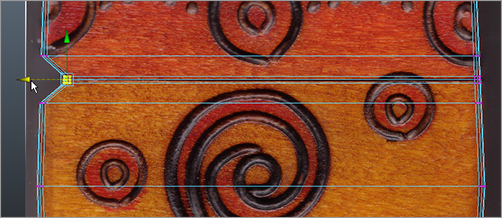
Figure 6-159: Select this edge loop, and scale it to create an indent line where the lid meets the box.

23. Hide the reference planes again, and turn Shading back on for the cube in the Attribute Editor. Figure 6-160 shows the completed box. But there’s still a little snag. Notice the dark area where the lid meets the box, where you just created the slightly indented line. This is due to Normals. It makes the lid look like it’s angled inward.
24. Select the box, and choose Normals ⇒ Set Normal Angle. In the Set Normal Angle window that pops open, set the Angle to the default of 30, and click Apply and Close. Doing so fixes the darkening. For more on Normals, see the note in this section. Select the box, and delete its history.
Figure 6-160: The completed box needs one more adjustment.
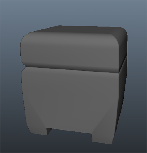
Figure 6-161: The box now looks right.
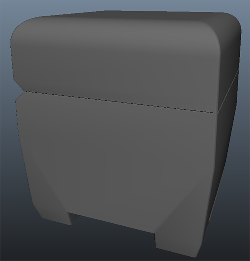
You’re finished with the modeling portion of this decorative box. In the following chapters, you’ll texture, light, and render the box with photorealism in mind. You can load boxModel.mb from the Scenes folder in the Decorative_Box project on the CD to compare your work.
Normals
Normals are imaginary lines that are perpendicular to a mesh’s poly face and that define sides for that face. They also help determine how a renderer, such as mental ray, shades the surface. In some cases when you’re modeling, you may notice an action that causes part of your model to display a darkened area as you see in the decorative box in Figure 6-160. By manually setting a Normal angle for the box as you did in step 24 of the exercise, you override the seeming display error. You’ll learn more about Normals in Chapter 7.