Modeling with Simple Deformers
In many ways, deformers are the Swiss Army knives of Maya animation, except you can’t open a bottle with them. Deformers are handy for creating and editing modeled shapes in Maya. These tools allow you to change the shape of an object easily. Rather than using CVs or vertices to distort or bend an object manually, you can use a deformer to affect the entire object. Popular deformers, such as Bend and Flare, can be powerful tools for adjusting your models quickly and evenly, as you’re about to see.
Nonlinear deformers, such as Bend and Flare, create simple shape adjustments for the attached geometry, such as bending the object. You can also use deformers in animation to create effects or deformations in your objects. We’ll explore this later in the book.
Modeling Using the Bend Deformer
Figure 5-50: Create a cylinder to bend.

Let’s apply a deformer. In a new Maya scene, you’ll create a polygonal cylinder and bend it to get a quick idea of how deformers work. Follow these steps:
1. Choose Create ⇒ Polygon Primitives, and turn on Interactive Creation. Then, choose Create ⇒ Polygon Primitives ⇒ Cylinder. Click and drag to create the base. Make it a few units in diameter; the exact sizing isn’t important here. Click and drag to make the height of the cylinder 7 or 8 units, as shown in Figure 5-50. Make sure your create options are set to the defaults so that they’re consistent with these directions.
To make sure the settings are at their defaults, open the command’s Options box and click the Reset Settings button.
Figure 5-51: Creating the Bend deformer
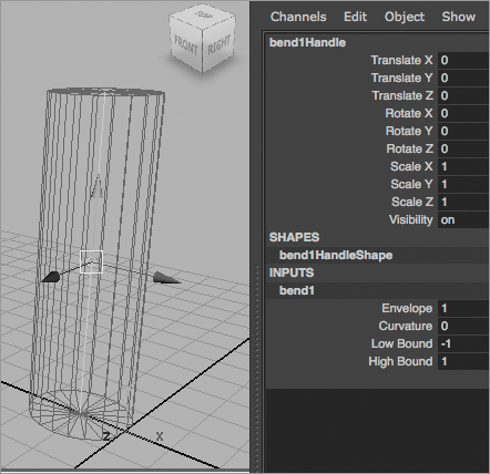
2. Let’s jump right in and create the Bend deformer. With the cylinder selected, switch to the Animation menu set by pressing F2 and choosing Create Deformers ⇒ Nonlinear ⇒ Bend. Your cylinder turns magenta, and a thin line appears at the center of the cylinder, running lengthwise. Figure 5-51 shows the deformer and its Channel Box attributes. Depending on your settings, your deformer may be created in a different axis than the one pictured. You can reset the deformer’s options as needed. Click bend1 in the Channel Box to expand the deformer’s attributes shown in the figure.
Figure 5-52: Notice the problem with this cylinder?

3. Click Curvature, and enter a value of 1. Notice that the cylinder takes on an odd shape, as shown in Figure 5-52. The Bend deformer itself is bending nicely, but the geometry isn’t. As a matter of fact, the geometry is now offset from its original location. It’s offset because there aren’t enough divisions in the geometry to allow for a smooth bend.
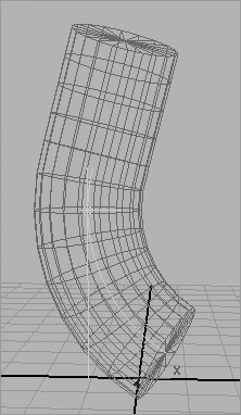
4. Select the cylinder, and click polyCylinder1 in the Channel Box to expand the shape node’s attributes. Enter a value of 12 for the Subdivisions Height attribute (see Figure 5-53), and your cylinder will bend with the deformer properly, as shown in Figure 5-54.
5. Try adjusting the Bend deformer’s Low and High Bound attributes. This allows you to bend one part of the cylinder without affecting the other. Figure 5-55 shows the cylinder with the Bend deformer’s High Bound set to 0.25 instead of 1. This causes the top half of the cylinder to bend only one quarter of the way up and continue straight from there.
Experiment with moving the Bend deformer, and see how doing so affects the geometry of the cylinder. The deformer’s position plays an important role in how it shapes an object’s geometry.
Figure 5-53: Increase Subdivisions Height to 12.

Figure 5-54: The cylinder bends properly now that it has the right number of divisions.

Figure 5-55: Using the High Bound to change the effect of the Bend deformer
Adjusting an Existing Axe Model
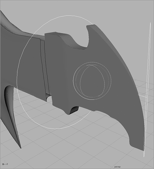
In this exercise, you’ll take an existing NURBS model of an axe and fine-tune the back end of the axe head. In the existing model, the back end of the axe head is blunt, as you can see in Figure 5-56. You’ll need to sharpen the blunt end with a nonlinear deformer. Open the AxeHead_v01.ma file in the Scenes folder of the Axe project on the CD, and follow these steps:
Figure 5-56: The axe head is blunt.

1. Select the top group of the axe head’s back end. To do so, open the Outliner, and select axeHead_Back (see Figure 5-57).
2. Click F2 to switch to the Animation menu set.
3. Create a Flare deformer by choosing Create Deformers ⇒ Nonlinear ⇒ Flare. The Flare deformer appears as a cylindrical object (see Figure 5-58).
Figure 5-57: Select the back of the axe head.
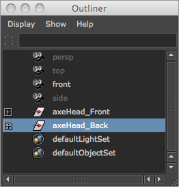
Figure 5-58: The Flare deformer appears as a cylinder.
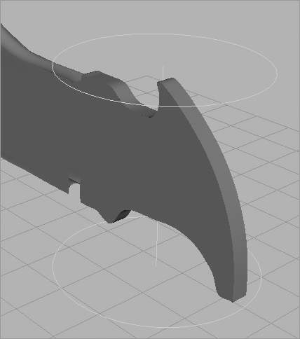
Figure 5-59: Rotate the deformer 90 degrees in the Z-axis.
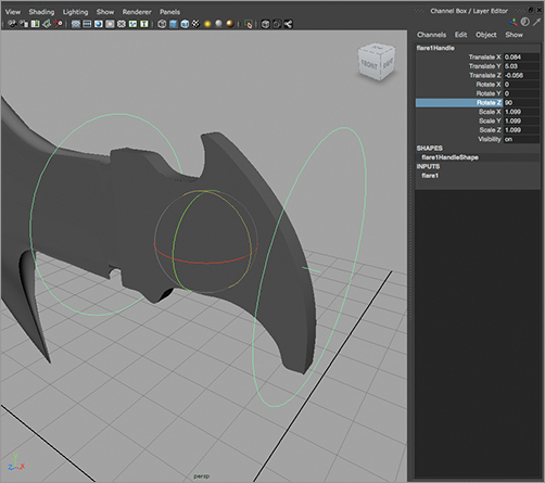
4. Rotate the deformer 90 degrees in the Z-axis, as shown in Figure 5-59.
5. Open the Attribute Editor (Ctrl+A), click the flare1 tab to access the Flare controls, and enter the following values:
| Attribute | Value |
| Start Flare Z | 0.020 |
| High Bound | 0.50 |
These values taper in the end of that part of the axe head, as shown in Figure 5-60. This is a much easier way of sharpening the blunt end than adjusting the individual CVs of the NURBS surfaces.
Deformers use History to distort the geometry to which they’re attached. You can animate any of the attributes that control the deformer shapes, but in this case you’re using the deformer as a means to adjust a model. When you get the desired shape, as shown in Figure 5-61, you can discard the deformer. However, simply selecting and deleting the deformer will reset the geometry to its original blunt shape. You need to pick the axeHead_Back geometry group (not the deformer) and delete its History by choosing Edit ⇒ Delete by Type ⇒ History.
Figure 5-60: Sharpen the axe’s back edge.

Figure 5-61: Another view of the back of the axe head with the Flare deformer