
For another foray into a skeletal system, you can give yourself a hand—literally. You’ll use a skeleton to deform the geometry and animate it as a hand would move.
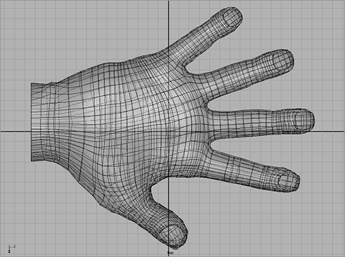
Load the file poly_hand_skeleton_v01.ma from the Poly_Hand_Anim project on the CD. The hand is shown in Figure 9-25.
You’ll use it to create a bone structure to make the hand animate. This is called rigging.
Figure 9-25: The hand mesh
Rigging the Hand
To create the first bones of the hand, follow these steps:
1. Maximize the Top view window. Switch to the Animation menu by using the drop-down menu or by pressing F2.
2. Activate the Joint tool by choosing Skeleton ⇒ Joint Tool. Your cursor turns into a cross.
3. Click at the base of the wrist to place the first joint. This will be the root joint of the hand.
4. Shift+click the bottom part of the palm.
5. Place joints down through the thumb from this second joint, according to the corresponding bones in Figure 9-26.
6. To start another string of joints into the palm, press the Up arrow key four times until you’re at the second joint at the base of the palm.
7. The next joint you place will be a branch from this joint. Place that joint in the middle of the palm. Place another joint up farther along the palm, and then branch it out to the index finger. Press the Up arrow key to return to that upper palm joint, and start a new branch into the middle finger.
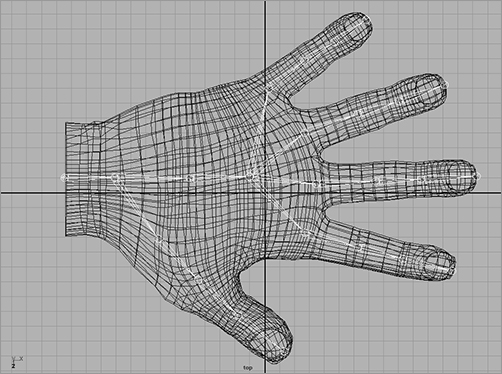
Repeat this procedure to place joints for the remaining fingers, as shown in Figure 9-27. With these joints placed, you have a simple skeleton rig for the hand. This rig allows you quite a bit of hand and finger movement.
Figure 9-26: Place the joints through to the tip of the thumb.
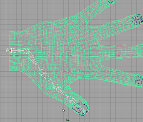
Figure 9-27: The joints in the hand
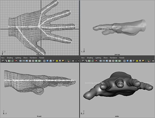
Check the other views (see Figure 9-28) to see where you need to tweak your joint positions to fit the hand. Ideally, you want the joints to be set inside your intended geometry in the same way that real bones are laid out.
Figure 9-28: Four views of the hand with initial placement of the joints
To position the joints, you can use either of two Maya tools: Move or Move Pivot. First, you’ll try the Move tool. Select the tip joint for the pinkie. It needs to be lowered into the pinkie itself. Select the Move tool (press W), and move it down into the tip of the pinkie. Now, move on to the top pinkie knuckle. Notice that if you move the knuckle, the tip moves as well. That’s not such a great idea.
Instead, it’s best to move joints as pivots. Because joints are nothing more than pivots, go into Move Pivot mode (press the Ins key, or the Home key on a Mac) to move joints. Select the top pinkie-knuckle joint, and move it with Move Pivot instead (press Ins or Home). Only the joint moves, and the bones adjust to the new position. Set the positions on the remaining joints to be inside the hand properly, as shown in Figures 9-29 and 9-30.
Figure 9-29: The joints of the hand placed properly in the geometry

Figure 9-30: Second view of the hand’s skeleton

Binding to Geometry
An integral part of rigging a character or an object with a skeleton is binding, also known as skinning. Binding is another way to attach geometry to a skeletal system. With the block man, you directly attached the whole pieces of geometry to the bones through parenting, whereas binding involves attaching clusters, or groups of vertices or CVs, of the geometry to the skeleton to allow the skeleton to deform the model. This is typically how skeletons are used in character animation work. (For more on grouping and parenting, refer to the Solar_System exercise in Chapter 2, “Jumping in Headfirst, with Both Feet.”)
The basic technique of binding a character is easy. However, Maya gives you tremendous control over how your geometry deforms.
Binding Overview
Binding is, in theory, identical to the Lattice deformer you saw in Chapter 5, “Modeling with NURBS, Subdivisions, and Deformers.” A lattice attached to an object exerts influence over parts of the model according to the sections of the lattice. Each section affects a NURBS surface’s CVs or a polygon surface’s vertices within its borders; and as a section of the lattice moves, it takes those points of the model with it.
Skeletal binding does much the same thing. It attaches the model’s points to the bones, and as the bones pivot around their joints, the section of the model that is attached follows.
By attaching vertices or CVs (depending on your geometry) to a skeleton, you can bend or distort the geometry. When a bone moves or rotates about its joint, it pulls with it the points that are attached to it. The geometry then deforms to fit the new configuration of the bones bound to it.
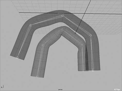
You can directly bind geometry to a skeleton in two ways: using Smooth Bind and using Rigid Bind. You can indirectly deform geometry using deformers and lattices attached to skeletons, but here you’ll use the direct methods. Figure 9-31 shows a rigid bind, and Figure 9-32 shows a smooth bind.
Figure 9-31: Rigid bind of a cylinder. The crease is pronounced.

Figure 9-32: Smooth bind of the cylinder shown in Figure 9-31. The crease is smoother, yet less defined.

Create a tall NURBS cylinder, with a span of 16 or more. The more spans you have in the deformable model, the better it will bend. Duplicate the cylinder, and move it over in your window. Now, in the front view, create a four-bone (five-joint) skeleton that starts at the bottom of the first cylinder and goes straight up the middle, ending at the tip. Duplicate the skeleton, and move it to the center of the second cylinder.
Creating a Rigid Bind
A rigid bind is the simpler of the two, because only one surface point (vertex or CV) is affected by a joint at a time. A rigid bind groups the CVs of a NURBS or the vertices of a polygon into joint clusters that are then attached to the bones. No one surface point is influenced by more than one joint.
Bending a model about a joint with a rigid bind yields a more articulate crease than a smooth bind. A smooth bind allows more than one joint to affect the CV or vertex, resulting in a more rounded and smooth bend.
To create a rigid bind, select the first skeleton and Shift+click its cylinder. In the Animation menu, choose Skin ⇒ Bind Skin ⇒ Rigid Bind ❒.
In the option box, you’ll find that almost everything you need is already set to the default. The Bind To parameter lets you rigid-bind the entire skeleton to the geometry or rigid-bind only the joints selected. Using Selected Joints gives you the option of using just part of a skeleton system to rigid-bind, which also gives you flexibility in how your rig affects the model. Leave that option set to Complete Skeleton to attach the whole thing.
Click the Color Joints check box to set a different color for each joint in the bind, which can make for an easier workflow. The Bind Method parameter deals with how the points in the model are attached. The default, Closest Point, organizes the points into skin point sets according the joint to which they’re closest. They’re then assigned to be influenced by that joint only.
The Partition Set option lets you define your own points before you bind and select which points are set to which joints. If you define a partition set for each joint you have, Maya assigns each set to the nearest joint. For example, you can define some points at the top of the surface to be a part of a set controlled by a joint in the bottom part. Closest Point is the best option for most work.
Use the defaults, turn on Color Joints, and click the Bind Skin button in the option box. The root of the skeleton is selected and the cylinder turns magenta, signifying that it has input connections (such as history).
Creating a Smooth Bind
A smooth bind allows a joint to influence more than one skin point on the model. This lets areas of the model farther from the joint bend when that joint rotates. Joints influence points to varying degrees between 0 and 1 across the surface, decreasing in influence the farther the point is from the joint. The multiple influences on a point need to add to 1 across all the joints that influence it. Maya automatically generates the proper influence amounts upon binding, although the animator can change these values later.
To create a smooth bind, select the second skeleton and its cylinder, and choose Skin ⇒ Bind Skin ⇒ Smooth Bind ❒.
In the option box, you’ll find the familiar Bind To parameter. You’ll also find, under the Bind Method drop-down menu, the options Closest in Hierarchy and Closest Distance. Choosing Closest in Hierarchy assigns the skin points to the nearest joint in the hierarchy. This option is most commonly used for character work, because it pays attention to the way the skeleton is laid out. For example, a surface point on the right leg wouldn’t be affected by the thigh joint on the left leg simply because it’s near it on the model. Closest Distance, on the other hand, disregards a joint’s position in the hierarchy of the skeleton and assigns influences according to how far the point is from the joint.
Max Influences sets a limit on how many joints can affect a single point. Dropoff Rate determines how a joint’s influence diminishes on points farther from it. For example, with Smooth Bind, one shoulder joint can influence, to varying degrees, points stretching down the arm and into the chest and belly. By limiting these two parameters, you can control how much of your model is pulled along by a particular joint.
Using all the defaults is typically best. So, click Bind Skin in the option box to smooth-bind your second cylinder to the bones.
Bend both cylinders to get a feel for how each creases at the bending joints. Figure 9-33 shows the difference.
Figure 9-33: Rigid- and smooth-bound cylinders. The smaller cylinder is rigid bound, and the larger is smooth bound.
Detaching a Skeleton
If you want to do away with your binding, select the skeleton and its geometry and choose Skin ⇒ Detach Skin. The model will snap to the shape it had before the bind was applied and the joints were rotated. It’s common to bind and detach skeletons several times on the same model as you try to figure out the exact configuration that works best for you and your animation.
If you need to go back to the initial position of the skeleton at the point of binding it to the model, you can automatically set the skeleton back to the bind pose after any rotations have been applied to any of its joints. Simply select the skeleton and choose Skin ⇒ Go to Bind Pose to snap the skeleton and model into the position they were when you bound them together. It’s also best to set your skeleton to the bind pose whenever you edit your binding weights.
A Modeling Trick Using a Skeleton
An easy way to create bends and creases in a model is to create the surface without the bend and use a skeleton to deform it the way you want. You can then detach the skin and bake the history so that the surface retains its deformation but loses its connection to the skeleton. Bind your geometry to the skeleton chain using Smooth Bind or Rigid Bind. Bend the skeleton to deform the geometry, and then choose Skin ⇒ Detach Skin ❒. In the option box, set the History parameter to Bake History, and click Detach. The model will retain its deformed state but will lose all connections to the skeleton. This is just like using a Nonlinear or Lattice deformer on an object and then deleting the object’s history to rid it of the deformer. With a detached skin, however, you won’t lose any other history already applied to that object as you would if you deleted history through the Edit menu.
Binding the Hand: Rigid
Because you want definitive creases at the finger joints, you’ll use Rigid Bind for the hand.
Load your hand and positioned skeleton, or use the file poly_hand_skeleton_v02.ma from the Poly_Hand_Anim project on the CD. Now, follow these steps to rigid-bind the hand:
1. Select the skeleton’s root at the wrist, and Shift+click the top node of the hand. If you’re using the file from the CD, select the hand’s top node (handTopNode) to make sure you select the fingernails as well, as shown in Figure 9-34.
2. Choose Skin ⇒ Bind Skin ⇒ Rigid Bind ❒. Turn on Color Joints, and click the Bind Skin button in the option box. You’re bound and ready to animate the hand. The joints take on colors to help you identify them.
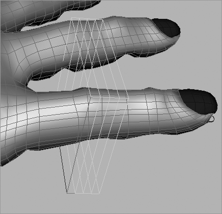
3. Select some of the finger joints, and rotate them. Notice how the model creases at the knuckles, as shown with the index finger in Figure 9-35. If you rotate far enough, the model will fold in over itself.
Figure 9-34: Select the root joint as well as the top node of the hand.

Figure 9-35: The crease at the knuckle is severe, and the geometry folds over into itself.

Editing a Rigid Bind
Having a rigid bind doesn’t mean your creases always have to be this hard. With flexors (basically lattices, as discussed in Chapter 5), you can smooth out specific areas of a joint for a better look. This is useful at shoulder joints or hip joints, where a crease such as on an elbow isn’t desired. In this case, it will help smooth out the knuckles so the geometry doesn’t fold over itself, as in Figure 9-35:
Figure 9-36: Creating a flexor

1. Choose Skin ⇒ Go to Bind Pose to reset your skeleton.
2. Select the middle knuckle of the index finger, and choose Skin ⇒ Edit Rigid Skin ⇒ Create Flexor to open the Create Flexor option box (Figure 9-36).
Figure 9-37: Creating a flexor at the middle knuckle
3. Notice that these options are similar to the lattice you created in Chapter 6, “Practical Experience,” to edit the model. You can adjust the number of divisions later through the Attribute Editor, so you don’t need to know exactly what you require before you create the flexor. Click Create to display a lattice at the joint position, as shown in Figure 9-37.
Figure 9-38: Scaling the flexor to fit better on the knuckle

4. In the Outliner, drill down to the jointFfd1LatticeGroup node now attached under that knuckle joint in the hierarchy. Select the lattice as well as its base so you can adjust the size and, if need be, position of the flexor, just as you did on the lattice work earlier. Resize the flexor so that it better conforms to the knuckle, and elongate it so that it covers more of the finger, as shown in Figure 9-38.
5. Scaling and positioning the flexor (when both lattice and base nodes are selected) makes the joint bend more smoothly, without affecting it more than necessary. By elongating the flexor here, you smooth out the knuckle’s bend, prevent the polygons from bending over each other, and still maintain a crisp crease, as shown in Figure 9-39.
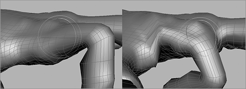
6. Create flexors for the other knuckles that need them. Be sure to scale the flexors to make the most efficient use of them and fit them only where they need to be fitted. Figure 9-40 shows how the finger reacts when bending with flexors at each joint.
Figure 9-39: The knuckle’s crease is now sharp, but the geometry doesn’t fold over itself as before.
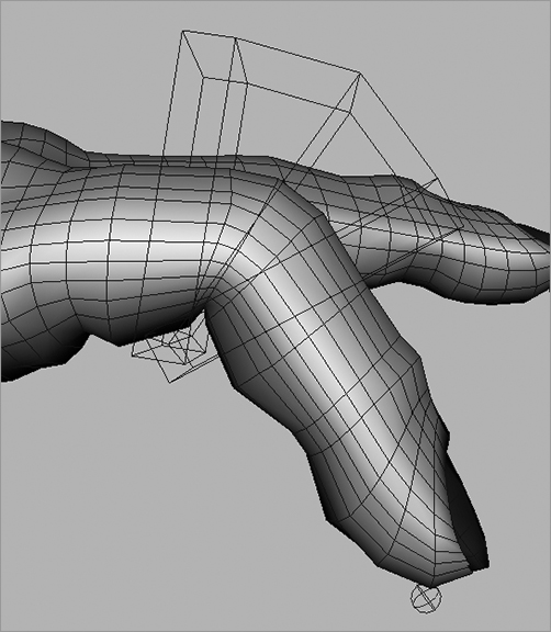
Figure 9-40: Flexors along the index finger

For reference, the scene poly_hand_skeleton_v03.ma from the Poly_Hand_Anim project on the CD has the hand rigid-bound with flexors on one finger. Start with it to create flexors for the rest of the fingers, and animate the hand, making some sign language positions, grabbing a pencil, or pressing a button.
Binding the Hand: Smooth
Now, try skinning the hand with Smooth Bind.
Load your prebound hand or poly_hand_skeleton_v02.ma from the Poly_Hand_Anim project on the CD. Now, follow these steps to smooth-bind the hand:
1. Select the root at the wrist and the top node of the hand (if you’re using the hand from the CD, make sure you have the nails as well). Choose Skin ⇒ Bind Skin ⇒ Smooth Bind.
2. Try rotating some of the knuckle joints to see how the fingers respond. Go back to the bind pose when you’re done.
3. Rotate the middle knuckle of the index finger down. Notice how the knuckle gets thinner the more you bend the finger there. Go to the top knuckle of the index finger, and rotate that joint. Notice that part of the hand moves with the finger. This is again exaggerated because the hand is polygonal, so its deformations seem more severe than a NURBS model of the same hand. Figure 9-41 shows the result of bending at the index finger.
Figure 9-41: Bending at the index finger causes some unwanted deformation.
Editing a Smooth Bind
You usually edit a smooth bind by painting skin weights. Because points on the model are influenced by multiple joints in a smooth bind, you need to adjust just how much influence is exerted by these joints on the same points:
1. Make sure you’re in Shaded mode (press 5). Select the hand, and then choose Skin ⇒ Edit Smooth Skin ⇒ Paint Skin Weights Tool ❒.
You paint skin weights on the affected geometry and not on the joints themselves, so you need to select the model and not the skeleton before invoking this tool.
2. Your hand should turn black, with a bit of light gray at the wrist. The option box appears, listing the joints that are connected to the hand, as shown in Figure 9-42.
Figure 9-42: The option box for the Paint Skin Weights tool
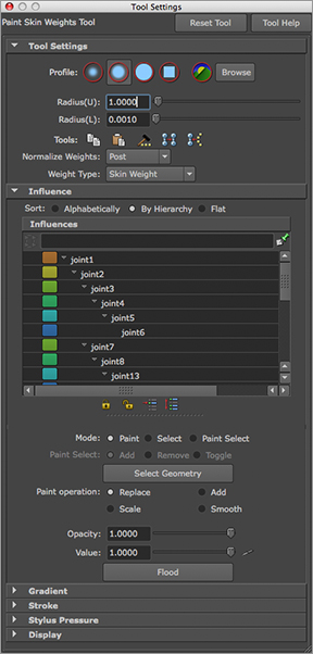
3. The color value (between white and black) determines how much binding influence the selected joint in the option box is exerting on that part of the geometry. It’s best to name your joints properly so that selecting from this window is easier and more intuitive. If you loaded the file from the CD, you need to name the joints yourself to organize the scene and make working with it easier.
4. In the option box, make sure the Paint Operation button under the Paint Weights section is set to Replace. Change the Value slider to 0. In the Tool Settings section, Radius(U) and Radius(L) govern the size of your brush. In the Influence section, make sure the Opacity slider is set to 1.
To change the size of your Artisan Brush while you’re painting weights, you can hold down the B key and drag the mouse left or right to adjust the radius of the brush interactively.
5. Click and paint the black value around parts of the hand and palm that shouldn’t be affected by the index finger bending at its top knuckle, as shown in Figure 9-43.
Skin weights must always be normalized in a smooth bind, meaning the values have to add up to 1. When you reduce the influence of a joint on an area of the surface, the influence amount is automatically shifted to other joints in the hierarchy that have influence over that area; those joints are now more responsible for its movement.
6. Smooth out the area where it goes from white to black. In the Tool Settings window, set Paint Operation to Smooth. Right-click to smooth the area around the knuckle for a cleaner deformation. Your index knuckle should now bend beautifully.
Figure 9-43: Paint the new weights to avoid unwanted deformations in the hand.

You can exit the Paint Skin Weights tool by selecting another tool (press W for Translate, for example), and your view will return to regular Shaded mode. Try bending the rest of the fingers and painting their influences; then, animate the hand, making gestures or grabbing an object using FK animation to set keys on the rotations.
When you paint weights on polygons, keep in mind that you’re painting using the UVs. You may need to re-create the UVs of a polygonal mesh with a UV projection map for the Paint Weights tool to function properly, especially when you’re importing and exporting the weight maps from one mesh to another (a procedure you won’t encounter until later in your Maya experience).
The scene poly_hand_skeleton_v04.ma from the Poly_Hand_Anim project on the CD has the hand smooth-bound with painted weights on the index finger for your reference. Try painting the other knuckles as needed for your animation.
Rigging work is essential for getting a good animation from your model. In a professional shop, it usually falls under the domain of a technical director (TD) who oversees the setup of characters and may also model their geometry. The more time I spent rigging scenes for the animators when I was a TD on the television show South Park, the easier and faster they were able to accomplish their animations.