
Photoreal Mapping: The Decorative Box
With all the references you can find to any given object on the Internet, why not use real photos to create the textures for a model? That’s exactly what you’ll do here, with the decorative box you modeled in Chapter 6, using pictures of the real box.
You’ll take this texturing exercise one important step further in Chapter 11 and experience how you can add detail to an object through displacement mapping, after you assign the colors in this chapter. This will allow you to add finer detail to a model without modeling those details.
Setting Up UVs (Blech!)
The UVs on the decorative box aren’t too badly laid out by default, as you can see in Figure 7-111. The only parts of the box that are missing in the UV layout are the feet. That is a common issue when extruding polygons: their UVs are rarely laid out automatically as you extrude them. Frequently, they’re bunched up together in a flat layout that is difficult, if not impossible, to see in the UV Texture Editor.
First, you have to make room for the feet UVs:
1. Select all the UVs for the entire box in the UV Texture Editor. Press R for the Scale tool, and scale everything down uniformly to gain some space in the normalized UV space, shown in Figure 7-112.
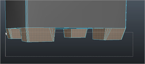
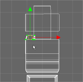
2. Now for the tedious part: you have to create new UVs for the four feet and then move them to where they should be in the full box’s UV layout. Go into Component mode, and select the poly faces for the four feet, as shown in Figure 7-113.
Figure 7-111: The feet UVs are missing from the box model.

Figure 7-112: Scale all the UVs down a bit.

Figure 7-113: Select the faces for the feet.
3. With the faces selected, go to the main Maya window. In the Polygons menu set, select Create UVs ⇒ Automatic Mapping. The feet now have UVs that you can see in Figure 7-114. However, they’re all over the place. You have to individually select and move each face of each foot to its appropriate place on the box’s overall UV layout.
4. Select all the feet UVs in the UV Texture Editor, scale them all down uniformly together, and move them off to the side. (See Figure 7-115.) You’ll position and scale them to fit properly soon.
Figure 7-114: The automatic UV creation puts the UVs everywhere.

Figure 7-115: Separate the feet UVs to the side, and scale them down.

Laying out UVs can be a time-consuming affair, as you’ve seen with the wagon. Although it’s recommended that you follow along with this exercise to lay out UVs for the box, because doing so will give you more practice and experience with UVs, you can skip straight to color-mapping the box in the next section by loading the file boxTexture01.mb in the Scenes folder of the Decorative_Box project on the CD.
5. Now comes the task of figuring out which UV fits where. Start with the left foot on the front of the box. In the persp window, select one front face of the front foot, left side on the front of the box. (See Figure 7-116.)
6. Right-click in the UV Texture Editor, and choose UV from the marking menu. Select a single UV point on the face that appears in the UV Texture Editor window, as shown in Figure 7-117. As soon as you make the selection, the UV Texture Editor shows you the UVs for the entire box. Because you moved the feet UVs to the side, your UV Texture Editor should look like the one in Figure 7-118, with a green point showing the single selected UV.
7. In the UV Texture Editor, choose Select ⇒ Select Shell. The UVs for the entire front part of that foot are selected. The UVs are sideways, so choose Polygons ⇒ Rotate ❒. Set the rotation angle to 90, and click Rotate UVs. The front of this foot should now resemble the actual foot, although the scale is still off.
Figure 7-116: Select the one face on this foot on the front of the box.

Figure 7-117: Select one UV point on that face in the UV Texture Editor window.
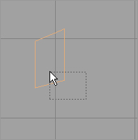
Figure 7-118: The UV Texture Editor shows you that one selected UV as well as the UV layout for the rest of the box.

Position the UV layout of this foot onto the front of the box, as shown in Figure 7-119. Scale down the UVs to match the size of the foot in the model, more or less. Keep in mind that the box-front UV layout is upside down in the UV Texture Editor.
Figure 7-119: Move these UVs to the front of the box where that foot belongs.
8. Select a front face of the back foot behind the front foot, as shown in Figure 7-120. Sounds confusing, but the figure shows you which face to select. In this figure, you’re looking at the front of the box. The UV Texture Editor shows the UV layout for that part of the foot. Choose Select ⇒ Select Shell to grab the entire front of that back foot. (See Figure 7-121.)
Figure 7-120: Select a front face of the back foot.
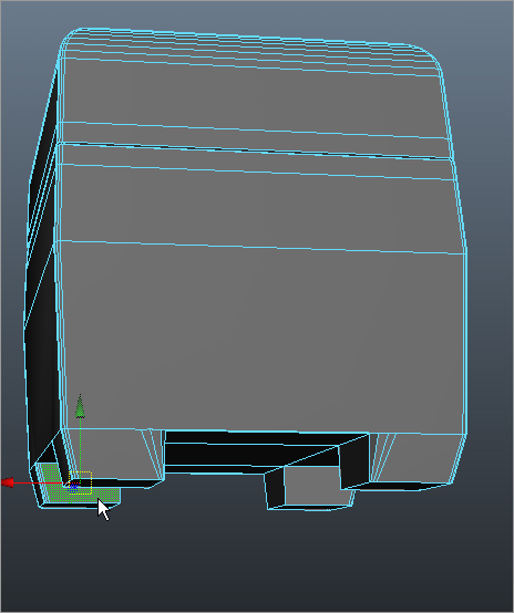
Figure 7-121: The UV Texture Editor shows the UV layout for that part of the back foot.

Figure 7-122: Place the front of the back foot’s UVs.
9. The back foot’s UVs lie directly behind the front foot’s UVs, which you laid out in step 7. Rotate the UVs (90 degrees again) with the Polygons ⇒ Rotate command, as you did before, and then position and scale the UVs as shown in Figure 7-122. They fit exactly behind the front foot.
10. Repeat steps 5 through 9 for the front and back feet on the front right side of the box.
Figure 7-123: Place the UVs for the fronts of the two feet on the right side of the box’s front.
11. Let’s move to the right side of the box. Select a front face for the foot on the left on the right side of the box. Again, it sounds confusing, but reference Figure 7-124 for clarification. You should be getting the hang of what you’re doing. Save your work.
12. In the UV Texture Editor, select one UV from the selected face, and then choose Select ⇒ Select Shell. (See Figure 7-125.)
13. Check to see where the UVs for the right side of the box are laid out in the UV Texture Editor in the earlier Figure 7-111. Rotate, scale, and place these foot UVs as shown in Figure 7-126.
Figure 7-124: Selecting a face for the left foot on the right side of the box
Figure 7-125: The UV shell for the foot you’re working on
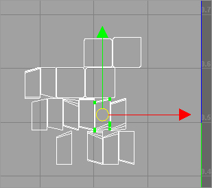
Figure 7-126: Place the right side foot UVs.

14. Repeat the procedures to move the UVs for the front and back feet for the right side of the box, as shown in Figure 7-127. Make sure you’re using Select ⇒ Select Shell, to ensure that you have the entire UV shell selected before orienting and moving the feet UVs.
Figure 7-127: Placing the feet for the right side of the box

15. Repeat the procedures for the feet seen from the back side of the box, so the foot UVs are all laid out similar to Figure 7-128.
16. Repeat the procedures to lay out the UVs for the feet seen from the left side of the box, as shown in Figure 7-129.
Figure 7-128: The feet are laid out for the back side of the box.

Figure 7-129: The feet are laid out for the left side of the box.

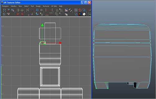
17. All that remain are the bottoms of the feet, as seen in the UV Texture Editor in Figure 7-130. Move the entire shell of the box bottom up to get some space between it and the box front layout.
18. Using the same procedures as before (selecting the shell, and rotating, moving, and scaling each UV shell), place the bottoms of the feet where they belong, as shown in Figure 7-131.
When you’re all done, your UV Texture Editor should resemble the one shown in Figure 7-132. Because the box’s decorations are seamless from the top of the box down to the four sides, let’s layout the UVs to make painting and editing in Photoshop easier.
Figure 7-130: The bottom UVs for the feet are selected and shown in the small square highlights in the image on the right and are also shown selected in the UV Texture Editor on the left.

Figure 7-131: Move the bottom UVs to the underside of the box.
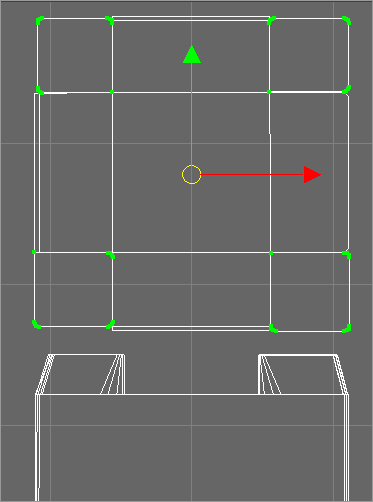
Figure 7-132: Finally, you’re finished with UVs.

Individually select the UVs for the right and left sides of the box, and rotate and position them to match Figure 7-133. Line up the sides to the top as closely as you can.
This was quite a tedious exercise. UV layout is a chore, but when it’s completed, you’re free to lay out your textures. You can check your work against the file boxTexture01.mb in the Scenes folder of the Decorative_Box project on the CD. You can also take a much needed breather. I sure hope you’ve been saving your work!
Figure 7-133: Place the sides of the box around the top, lining them up as closely as possible.

Color Mapping the Box
Now that you have a good UV layout, you can output a UV snapshot and get to work editing your photos of the box to make the color maps. Start with the following steps:
Figure 7-134: Setting the UV Snapshot options
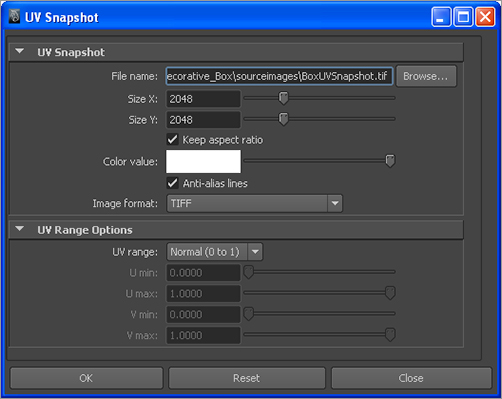
1. Select the box, and open the UV Texture Editor window. From the UV Texture Editor menu, select Polygons ⇒ UV Snapshot. In the UV Snapshot window, set Size X and Y to 2048. Change Image Format to TIFF.
Click the Browse button, and select a location for your UV snapshot image. Generally, the project’s Sourceimages folder is the best place for it. Make sure you don’t write over the UV snapshot already created for you. Type in a name for your UV snapshot, and click OK to create the image. Figure 7-134 shows the option box, and Figure 7-135 shows the UV snapshot image.
Figure 7-135: The UV snapshot for the decorative box, shown as black lines on white. You may see white lines on black in Photoshop.

2. Open the UV snapshot image in Photoshop or your favorite image editor, and set it as its own layer. Rename the layer to UV Snapshot. I’ve done the heavy lifting for you and have prepared five photos of the decorative box that you can use to map the model. Figure 7-136 show the photos of the box. This image file is included as lineup.jpg in the Sourceimages folder in the Decorative_Box project on the CD.
Figure 7-136: Photos of the box

3. As you’ve probably guessed, you need to copy and paste the photos to their respective views over the UV Snapshot layer. Open the lineup.jpg file in Photoshop alongside the UV snapshot. Marquee-select a box around the top image (the one at left in Figure 7-136), and copy it (Ctrl+C or Edit ⇒ Copy in Photoshop).
4. Go to the UV snapshot image in Photoshop, and paste the image on top. Rename the new layer to Box Top, and set the layer’s Opacity to 50% so you can still see the UV layout, as shown in Figure 7-137.
Figure 7-137: Paste the top image onto the UV snapshot image.

5. Use the Scale function in Photoshop (Edit ⇒ Transform ⇒ Scale) to move and scale the top image to fit over the top of the UV layout, as shown in Figure 7-138. Make sure you scale the box-top image uniformly to keep it from distorting. You can do this by holding the Shift key as you scale the image up or down.
These photo images of the box have been retouched and painted to create an overlap. This means that parts of the sides of the box show in the top image. As you can see in Figure 7-138, the top image extends slightly all around the four sides. This allows the different parts of the texture map (top and four sides) to overlap and blend with each other better when put on the model.
Save your work as boxColorMapWork01.tif in the project’s Sourceimages folder. Make sure you’re saving the TIF file with layers to preserve your layer work. You can also save the file as a PSD to preserve the layers.
Figure 7-138: Position and scale the top image in Photoshop to line up with the UVs of the top of the model. Notice the overlap of the sides and the top.

6. Marquee-select the right-side image of the box (immediately to the right of the top image in lineup.jpg), and copy it. Paste it into boxColorMapWork01.tif in Photoshop. Do your best to align the right-side image with the top image, using the features of the box to line them up, as you can see in Figure 7-139. You can fix this later by adjusting both the map and the UVs on the box for a tighter fit. For now, be fairly accurate, and leave the finesse for later. Save the file as boxColorMapWork02.tif.
Figure 7-139: Align the right-side image with the right-side UVs.

Figure 7-140: Copy, paste, and line up the box sides and the back to their respective UV areas.

Figure 7-141: The color map layout

7. Use the same procedures in Photoshop to line up the other sides of the box, as shown in Figure 7-140. Set the box-top image to be the topmost layer, make sure all the layers are at 100% opacity, and then turn off the UV Snapshot layer so it’s not visible.
Save the final Photoshop file as boxColorMap.tif, again keeping all the layers. (Change the name if you don’t wish to overwrite the file already created for you in the Sourceimages folder.) Then, resave the file as a JPEG called boxColorMap.jpg. This is the file you’ll map. (See Figure 7-141.)
Mapping the Box
Let’s map this color image to the box and see how it fits. Based on rendering the box, you can make adjustments to the UVs and the image map to get everything to line up. This, of course, requires more Photoshop and/or image-editing experience, which could be a series of books of its own. If you don’t have enough image-editing experience, have no fear: the images have been created for you, so you can get the experience of mapping them and learn about the underlying workflow that this sort of texturing requires. Follow these steps:
Figure 7-142: The color map’s file node

1. Back in Maya, open the Hypershade window, and create a new Phong shader. Open the Attribute Editor, click the Map button (![]() ) next to the Color attribute, and select File.
) next to the Color attribute, and select File.
2. Double-click the file1 node to open the Attribute Editor. Click the folder icon next to the Image Name attribute, navigate to the Sourceimages folder for the project, and select the boxColorMap.jpg file (not the TIF file). The icon in the Hypershade doesn’t show the image because it’s a large file. (See Figure 7-142.)
Figure 7-143: The icon is refreshed.

3. Right-click the file1 node, and choose Refresh Swatch. The boxColorMap image is displayed as the file1 icon. (See Figure 7-143.)
4. Select the box, and assign the Phong shader it. Rename the Phong to boxShader. In the persp panel, press 6 for texture view. The color map is fairly well aligned on the model. Not bad! (See Figure 7-144.)
Figure 7-144: The color map fits pretty well already. But there are a few lineup issues at the edges.
5. Render a frame to see how the box looks. Notice that there are small lineup issues at the edges where the sides meet and where the top meets the sides. Save your Maya scene.
This gives you a pretty good place to work from. You need to adjust the color map image to be more seamless. The scene file boxTexture02.mb in the Scenes folder of the Decorative_Box project on the CD will catch you up to this point.
Figure 7-145: A render of the box so far

Photoshop Work
This is where image-editing experience is valuable. From here on, it’s all about working in Photoshop to line up the sides to the top and the sides to each other to minimize lineup issues and yield a seamless texture map. Although we won’t get into the minutia of photo editing here, we’ll show the progression of the images and the general workflow used in Photoshop to make the color map’s different sides and top line up and or merge better. The images have already been created and are on the CD under the Sourceimages folder for this project.
First, using masking in Photoshop, spend some time feathering the intersection of the box’s sides in boxColorMap.jpg so there is no hard line between the different sides and the top. Figure 7-146 shows a smoother transition between the different parts. This image has been created for you: it’s boxColorMap02.jpg in the Sourceimages folder. Make sure you don’t overwrite that file if you’re painting your own.
Figure 7-146: Use masks to feather the transitions between the different parts of the box.

Figure 7-147: There are blank areas on the box as well as a little distortion.

In Maya, replace the original boxColorMap.jpg with boxColorMap02.jpg. Render and compare the difference. The top and front should merge a little better. In the persp panel, orbit around the box in Texture View mode (press 6) to see where else there are lineup issues. In some cases, as you can see in Figure 7-147, gray or black is mapped onto the box on its right side, and there is a warped area. Also, the crease where the lid meets the box is lower than you’ve modeled.
The blank areas on the box are outside the bounds of the image in the Photoshop image and can be fixed by adjusting the UVs in Maya. The same goes for the distorted areas on the side of the box—you just need to adjust the UVs:
1. Select the box, and open the UV Texture Editor window. Figure 7-148 shows the primary areas for you to work on.
2. In the UV Texture Editor, select the UVs (right-click and choose UV) shown in Figure 7-149 on the left. Press W for the Move tool, and realign the UVs to the seam where the lid meets the box, as shown in Figure 7-149 on the right. As you make the changes in the UV Texture Editor, you should immediately notice them in the persp window (as long as you’re in Texture View mode).
Figure 7-148: Here are the main problems to fix.
Figure 7-149: Move the UVs.

3. Look at the image on top in Figure 7-150. Move the appropriate UVs to align the edge of the UV layout to the image for the right side of the box, as shown on the bottom of Figure 7-150.
4. The box’s distortion is gone, and the texture fits much better. But notice in the image on the left in Figure 7-151 that the right side of the box and the back of the box don’t line up perfectly. Using the texture view in the persp window and the UV Texture Editor, go around the box in its entirety and adjust the UVs so that they all line up to the image in the UV Texture Editor and that the sides line up at the edges of the box. Figure 7-151’s image on the right shows correctly lined up UVs for the right side/back side of the box.
Be careful when you’re selecting the UVs of one side so you don’t select UVs from an adjacent side in the UV Texture Editor.
Figure 7-150: Line up the UVs to the image for the right side of the box.
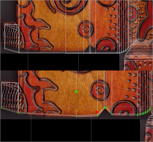
Figure 7-151: Line up the UVs for the right side/back side edge of the box.
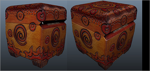
Figure 7-152 shows the UV Texture Editor and a persp view of the box with UVs lined up and ready to go. You can compare your work to the scene file boxTexture03.mb in the Scenes folder of the Decorative_Box project on the CD. Render a few different views to take in all the hard work. In Chapter 10, you’ll light the box and prepare it for rendering; and in Chapter 11, you’ll use displacement maps created from these photos to detail the indentations and carvings that are in the actual box. You’ve had enough excitement for one chapter.
Figure 7-152: The UVs laid out for the decorative box
