
In this section, you’ll add shaders to a NURBS modeled axe to make it look real; in the next chapter, you’ll import this axe into an animation exercise. Starting animation on a project and then replacing it with a finished and textured model is a fairly common practice with Maya.
Load axe_texture_A.mb from the Axe project on the CD.
You’ll start by texturing the metal parts of the axe. Even though you can find a good metal to use for your axe head in Maya’s shader library or on Autodesk’s website, for this exercise you’ll make a simple metal from scratch. Because the look of real metals is greatly affected by their surroundings (that is, by the reflections of the environment), metal is one of the toughest materials to create and to light. In many cases, metals are lighted and rendered with HDR Image Based Lighting, a technique too advanced for this book. It will be easier to learn when you’re more familiar with lighting and rendering with Maya.
Autodesk’s website lists several premade shaders for your use. Maya also includes a shader library on its installation CD.
The Metal Axe Head
First, set up your render parameters so that you can render out your axe while you’re tweaking the Metal shader to get it right:
1. Choose Window ⇒ Rendering Editors ⇒ Render Settings, or click (![]() ) in the menu bar to open the Render Settings window. Make sure Render Using is set to Maya Software.
) in the menu bar to open the Render Settings window. Make sure Render Using is set to Maya Software.
2. In the Image Size section under the Common tab, set Presets to 640 × 480. In the Anti-Aliasing Quality section under the Maya Software tab, use the Intermediate Quality preset. This will give you a good look for the final render with a short render time.
3. Open the Hypershade window, and click Phong under the Create pane on the left. A new Phong shader shows up in both the top and the bottom parts of the Hypershade window.
4. Double-click the phong1 shader node in the Hypershade window to open the Attribute Editor, and name the shader Metal.
5. Click the gray swatch next to the Color attribute to open the Color Chooser. Select a light blue-gray. In the Slider section, the HSV values should be something like H: 207, S: 0.085, and V: 0.80. Click Accept.
6. Back in the shader’s Attribute Editor, click the gray swatch for Specular Color. By changing this color, you control the hue and brightness of the highlights on this surface. Use a bright faded blue with HSV values of H: 208, S: 0.20, and V: 0.90.
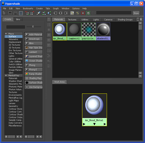
Figure 7-14: The Metal shader’s material node, as shown in the Hypershade window
7. Increase the spread of the specular highlights by changing Cosine Power from the default of 20 to 2.0. Doing so creates a large area for the bright highlights, implying a polished reflective surface.
8. To assign the shader to the surfaces, select both sides of the axe head. In the Hypershade, right-click the shader node (in either the upper or lower window), and choose Assign Material to Selection from the shortcut menu. Figure 7-14 shows the shader.
9. Make sure your perspective view is active, and click the Render the Current Frame button (![]() ) in the menu bar. Check out different angles of the axe, and render them to see how the metal axe head responds to the default lights that Maya inserts into the scene for your render.
) in the menu bar. Check out different angles of the axe, and render them to see how the metal axe head responds to the default lights that Maya inserts into the scene for your render.
This procedure creates a simple Metal shader that works well overall. To create a more polished look for the axe head, you can add a reflection to it using an Environment texture node. This node creates a 3D texture node in the scene that projects its contents onto the Material attribute to which it has been connected. As an object animates through the scene, different parts of the texture are reflected on its surface.
Figure 7-15: You can add a texture to a shader’s attribute by clicking the checkered Map button.
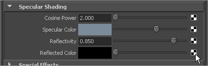
10. In the Metal shader’s Attribute Editor, click the Map button next to the Reflected Color attribute, as shown in Figure 7-15. Doing so attaches a new node to create a reflection and opens the Create Render Node window. Click the Env Textures section, and select Env Chrome. An environment texture will provide an interesting reflection.
11. Move the Reflectivity slider from 0.50 to 0.85. The higher this number, the more prominent the Reflected Color in the surface. Figure 7-16 shows the axe before and after a reflection. The Env Chrome reflection texture makes the axe look polished by reflecting a grid representing the ground and a bright blue sky.
Figure 7-16: The axe head before and after a reflection is mapped onto the shader
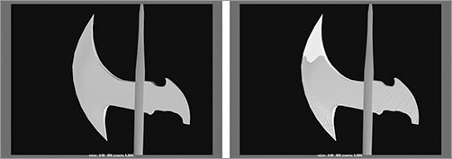
Figure 7-17: Use placement nodes in the scene to scale and position textures.

After you create the Env Chrome texture, you’ll see a green object in the Modeling windows at the origin, as shown in Figure 7-17. This is the Env Chrome’s placement node. You can manipulate this node just as you manipulate other Maya objects—in other words, move, rotate, and scale it.
Altering this will change how the environment chrome projects itself in the scene. For example, if you increase the size of this placement node, the grid showing in the reflection of the axe will get larger. For more on projections and placement nodes, see the “Texture Nodes” section later in this chapter.
The Wooden Handle
A glossy cherry wood would look good for the handle, so a Phong shader will be best:
1. In the Hypershade, choose Create ⇒ Materials ⇒ Phong. Set Diffuse to 0.70, Specular Color to a light gray, and Cosine Power to 50.
2. Click the Map button for the color. In the Create Render Node window, select Wood in the 3D Textures section. Figure 7-18 shows this texture in the Attribute Editor.
3. In the Wood Attribute Editor, adjust Filler Color to a nice reddish brown with an HSV of 8.5, 0.85, and 0.43. Change Vein Color to a darker version of the filler with HSV color values of 8.5, 0.75, and 0.08, respectively.
4. Change Vein Spread to 0.70, change Layer Size to 0.119, and darken Grain Color a bit by pulling the slider to the left, but not all the way, as shown in Figure 7-19. This gives you a nice dark cherry wood.
The Wood texture is a projected 3D texture; it’s projected from a source onto the object using a placement node, just like the Env Chrome on the axe head’s reflection. To assign the Wood texture from the Hypershade, select the handle, and right-click the shader to select Assign Material to Selection; or MMB+click and drag the icon onto the handle in the viewport. For more on projected textures, see the “Texture Nodes” section later in this chapter.
You can assign a shader to any object by MMB+clicking and dragging its icon from the Hypershade to the object in the viewport.
5. To see this dark texture on your object, create a new light in the scene. In the main menu, choose Create ⇒ Lights ⇒ Ambient Light. (For more on lights, see Chapter 10.) Open the Attribute Editor for the light by pressing Ctrl+A or by double-clicking its icon on the Lights tab in the Hypershade. Increase the Intensity attribute to 2.5.
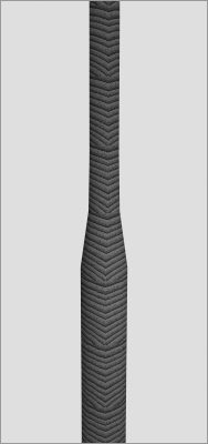
6. Render a frame of the axe handle up close, as shown in Figure 7-20. Notice how the wood repeats on the handle and creates an undesirable texture. You need to adjust the Wood texture’s placement.
Figure 7-18: The Wood texture in its Attribute Editor
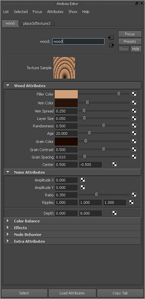
Figure 7-19: Set the Wood texture’s attributes.
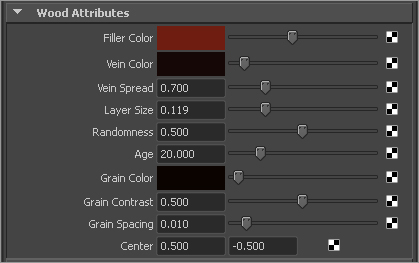
Figure 7-20: The Wood texture repeats too much by default.
7. To get to the Wood texture’s placement node, open the Hypershade. Drag the Wood shader to the Hypershade work area (bottom half). Right-click the wood, and choose Graph Network from the shortcut menu. You can also select it and click the Input Connections button (![]() ) at the top of the Hypershade. Figure 7-21 shows the shader nodes for the Wood Shader network in the Hypershade work area. The place3dTexture2 node connects to the wood2 node and gives it position information. The wood2 node then connects to the phong3 material node as a Color texture map.
) at the top of the Hypershade. Figure 7-21 shows the shader nodes for the Wood Shader network in the Hypershade work area. The place3dTexture2 node connects to the wood2 node and gives it position information. The wood2 node then connects to the phong3 material node as a Color texture map.
Figure 7-21: The Wood Shader network
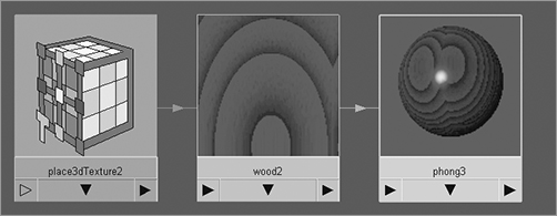
Figure 7-22: The wood’s placement node

8. Double-click the place3dTexture node to open its Attribute Editor.
9. Click the Fit to Group BBox button to position the placement node for the wood around the handle automatically. In your viewport, you see the green placement node around the handle, as shown in Figure 7-22.
10. Rendering a frame reveals that the wood still doesn’t look quite right. Select the placement node in the viewport, and rotate it in Z to 90. Click the Fit to Group BBox button again to rescale it to fit the handle. This doesn’t rotate it back to the way it was; it only scales it to fit the extent of the object to which it’s assigned.
11. Render another frame, and you see the wood veins running the length of the handle. It looks more like wood now, but it still repeats too much.
Instead of moving and scaling the texture placement node and rendering multiple times to get the wood placement just right, you can use Maya’s Interactive Photorealistic Rendering (IPR) to see your changes in real time. Choose the camera panel to render, and click the IPR Render the Current Frame button (![]() ) in the Status line; or choose Render ⇒ IPR Render Current Frame.
) in the Status line; or choose Render ⇒ IPR Render Current Frame.
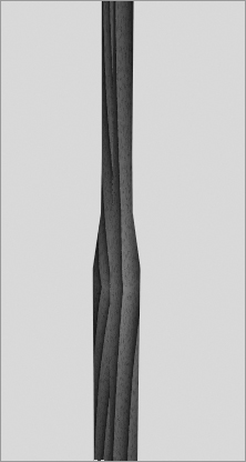
Figure 7-23: The wooden handle after the texture has been scaled and placed
The Render View window shows a lower-quality render of the axe. It prompts you to select a region to begin tuning. Drag a marquee selection in the Render View window around the handle. IPR refreshes that part of the window. Every change you make to the texture placement node prompts IPR to update that section of the render, giving you a fast update on the positioning and scale of the Wood texture.
12. Select the texture placement node, and scale it up in the three axes until you get a good-looking grain. Figure 7-23 shows a well-spaced wood grain.
The scene file axe_texture_B.mb in the Axe project on the CD will bring you up to this point.
Layered Shaders: The Metal Spike
Figure 7-24: The Layered shader in the Attribute Editor

Currently, the entire length of the handle is shaded as wood, including the top spike. The spike on the axe head should be metal like the axe head.
You can approach this in two ways: with geometry or with shaders. If you manipulate the NURBS geometry, you select a horizontal isoparm and detach the spike portion of the handle to make it a separate surface. You then assign a Metal shader to the new tip surface.
Using a shader instead of cutting up or creating more geometry can be desirable in many instances. For example, you may not be able to detach surfaces like this all the time.
The Layered shader is a normal surface shader that allows you to stack materials on top of each other to assign to a surface. You control which layer of material is exposed, and by how much, by assigning transparency values or textures to each layer. Use a Ramp texture to specify where on the handle the wood stops and the metal starts.
To create a Layered shader, follow these steps:
1. Select the axe handle, and in the Rendering menu set, choose Lighting/Shading ⇒ Assign New Material ⇒ Layered Shader to open the Attribute Editor, as shown in Figure 7-24. By default, the Layered shader contains a green layer in the top of the Attribute Editor window. From left to right, the layers are displayed in the order in which they appear from top to bottom as they’re assigned to the surface. (This means the leftmost shader in the Layered shader is on top of all the others.)
Choosing Lighting/Shading ⇒ Assign New Material is an easy way to create and assign a material without having to open the Hypershade.
2. Using the Hypershade, MMB+click and drag the metal material you’ve made into the top region of the Layered shader’s Attribute Editor window, under the Layered Shader Attributes section. To delete the default green material, click the Xed square beneath it. The Material Sample icon in the Attribute Editor turns into the metal.
Figure 7-25: The Layered shader with the wood on top of the metal

3. MMB+click and drag the wood material into the Layered shader’s Attribute Editor. Make sure it’s placed to the left of the metal material. If the materials are already in place, you can rearrange their order by MMB+clicking and dragging them left or right of the other materials in the Attribute Editor. Notice in Figure 7-25 that the Material Sample icon changed to the wood material. The wood is now the top layer, so only it will show until you give it some transparency to reveal metal at the tip.
You can see the names of the materials in the Layered shader by pointing to the icons.
4. Click the Wood Shader icon in the Layered shader’s Attribute Editor to highlight it. Notice that the Transparency Map button (as well as Color) is now a square with an arrow (![]() ) as opposed to the checkerboard you’ve seen before. Click this button to open the Attribute Editor for the wood material.
) as opposed to the checkerboard you’ve seen before. Click this button to open the Attribute Editor for the wood material.
When an attribute is already mapped, its Map button turns from a checkerboard to an Input Connection icon. Clicking it opens the Attribute Editor for whatever node is attached to that attribute. In this case, clicking the Map button opens its Attribute Editor because the wood material was assigned to this layer. Here you need to attach a transparency ramp to control where the metal tip starts and the wooden handle ends.
5. Click the Map button for the wood’s Transparency attribute. Create a Ramp texture node. Make sure the Normal radio button is checked and not the As Projection or As Stencil radio button.
6. In the ramp’s Attribute Editor, change Interpolation to None, and change Type to U Ramp.
7. Delete the middle (green) color by clicking the square to the right of green’s position. Select the bottom (red) color by clicking its round handle on the left of the ramp. Change the Selected Color attribute to white. Drag it all the way to the bottom of the ramp.
Figure 7-26: The Ramp texture is set on the wood’s Transparency attribute controls where the wood and metal meet.
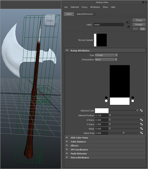
8. Select the top color (blue), and change it to black. Drag the handle down the ramp to a Selected Position of 0.105. Figure 7-26 shows the ramp position and the axe. If you’re in Texture Display mode in the perspective view (press the 6 key), you see that the tip of the model is a blue-gray color (metal) and the bottom of the handle is a reddish brown (wood). As you adjust the position of the white color on the ramp, notice how the spike and handle change.
9. In the Hypershade, choose Edit ⇒ Delete Unused Nodes to purge all unused shading nodes from your scene. Make sure your Layered shader and Metal shader are assigned, of course.
10. Render out a frame of the axe. Save this frame in the render buffer by clicking Keep Image (![]() ) in the Render View window. This keeps the image so you can scroll back to it for reference. A scroll bar appears at the bottom of the Render View window.
) in the Render View window. This keeps the image so you can scroll back to it for reference. A scroll bar appears at the bottom of the Render View window.
Figure 7-27: The wood grain changes as the axe moves.

11. Select the axe’s top node, and rotate it about 45 degrees in Z to angle it. Render a frame at this point. Notice how the grain of the wood has changed. Use the scroll bar to toggle back and forth and compare these two images, as shown in Figure 7-27.
When a projected texture, such as the wood, doesn’t “stick” to an object, and the object seems to move through the texture, the object is said to be swimming through the projection. The wood is being projected by the 3D placement node that you positioned to get the grain just right, so you need to group the texture node under the axe’s top node. When the axe moves, the texture will stick with it, maintaining its orientation with the axe.
12. Rotate the axe back to 0 in Z. Select the place3dTexture2 node from either the viewport (it’s the green texture you scaled to fit the handle as you see here) or the Outliner. Be careful not to use the Env Cube’s 3D placement node you used for the axe head reflection. In the Outliner, MMB+click and drag it under the axe’s topmost node, as shown in Figure 7-28.
Figure 7-28: Group the placement node for the handle under the axe geometry’s group node.

The file axe_texture_C.mb, in the Scenes folder of the Axe project on the CD has the final textured axe for your reference.
Now you have a fully textured axe. Because you used a Layered shader, you didn’t need to build another piece of geometry to represent a metal tip. You can embellish a model a lot at the texturing level. Although you may first consider using geometry, you can accomplish a number of tasks by using simple texturing tricks, such as those you used for the axe handle and its metal spike. The more you explore and experience shaders and modeling, the better you’ll be at juggling modeling with texturing to get the most effective solution.
You’ll begin texturing the red wagon from Chapter 6, “Practical Experience,” later in this chapter and then go into more detailed texturing with the decorative box, which you’ll then light and render in mental ray. For even more practice, try loading the locomotive model from Chapter 4, “Beginning Polygonal Modeling,” and texturing it from top to bottom. A great deal of independent geometry needs textures, some of which must be carefully placed with 3D placement nodes. Experiment with as many different ways of shading the locomotive as you can figure out.