
Texture nodes generate maps to connect to an attribute of a shader. There are two types of textures: procedural and bitmapped (sometimes called maps). Procedural textures use Maya’s own nodes’ attributes to generate an effect, such as ramp, checkerboard, or fractal noise textures. You can adjust each of these procedural textures by changing their attribute values.
A map, on the other hand, is a saved image file that is imported into the scene through a File texture node. These files are pregenerated through whatever imaging programs you have and include digital pictures and scanned photos. You need to place all texture nodes onto their surfaces through the shader. You can map them directly onto the surfaces’ UV values or project them.
Baking a Texture Projection
In the axe handle texturing exercise, you grouped the 3dplacement node for the wood grain to the handle of the axe to make the texture stick to the handle. But you can also bake the texture onto the axe handle by converting the texture projection to a file node. By baking the texture node, you convert the 3dplacement node into an image file that is then mapped to the color channel of the material, discarding the projection node, so you needn’t group it with the handle as you did earlier.
Follow these steps to bake the wood-grain texture to the axe:

1. Open the Hypershade.
2. Click to select the axe handle’s Layered shader node, and MMB+click and drag it to the work area of the Hypershade.
3. Right-click it, and select Graph Network to see all the nodes of the Layered shader (shown here).
4. Select the axe handle geometry, and then Shift+click the texture node wood2node in the Hypershade.
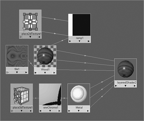
5. Choose Edit ⇒ Convert to File Texture (Maya Software) ❒. In the option box, select an X Resolution and a Y Resolution of 512 each, and click Convert and Close. If you get an error when you convert, you can choose Edit ⇒ Delete Unused Nodes and try again. The shader rebuilds itself to create a texture file, a material, and a shading group node that is automatically assigned to the selected geometry. Delete all unused nodes again to clean up the Hypershade window. Your new Shader network should appear as pictured here.
Notice that the 3dplacement node, as well as the Hypershade view, is removed from the scene. Your axe handle’s texture now sticks to the handle as a mapped-file texture instead.
UV Mapping
UV mapping places the texture directly on the surface and uses the surface coordinates for its positioning (called UVs). In this case, you must do a lot of work to line up the UVs on the surface to make sure the created images line up properly. What follows is a brief summary of how UV mapping works. You’ll get hands-on experience with UV layout with the red wagon and decorative box exercises later in this chapter.
Just as 3D space is based on coordinates in XYZ, surfaces have coordinates denoted by U and V values along a 2D coordinate system for width and height. The UV value helps a texture position itself on the surface. The U and V values range from 0 to 1, with (0,0) UV being the origin point of the surface.
Maya creates UVs for primitive surfaces automatically, but frequently you need to edit UVs for proper texture placement, particularly on polygonal meshes after you’ve edited them. In some instances, placing textures on a poly mesh requires projecting the textures onto the mesh, because the poly UVs may not line up as expected after the mesh has been edited. See the next section, “Using Projections.”
If the placement of your texture or image isn’t quite right, simply use the 2D placement node of the texture node to position it properly. See the section “Texture Nodes” later in this chapter for more information.
Using Projections
Figure 7-29: Selecting the type of map layout

You need to place textures on the surface. You can often do so using UV placement, but some textures need to be projected onto the surface. It’s common to project textures (when texturing polys, for example). A projection is what it sounds like. The file image, ramp, or other texture being used can be beamed onto the object in several ways.
You can create any texture node as either a normal UV map or a projected texture. In the Create Render Node window, clicking a texture icon creates it as a normal mapped texture. To create the texture as a projection, you must right-click the icon and select Create as Projection. (See Figure 7-29).
Figure 7-30: The projection node in the Attribute Editor
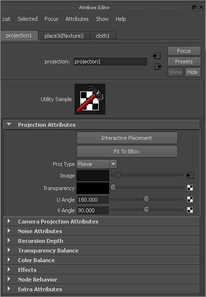
When you create a projected texture, a new node is attached to the texture node. This projection node controls the method of projection with an attached 3D placement node, which you saw in the axe exercise. Select the projection node to set the type of projection in the Attribute Editor. (See Figure 7-30.)
Setting the projection type will allow you to project an image or a texture without having it warp and distort, depending on the model you’re mapping. For example, a planar projection on a sphere will warp the edges of the image as they stretch into infinity on the sides of the sphere.
Figure 7-31: Assign a checkerboard pattern to the sphere and cone with Normal checked.
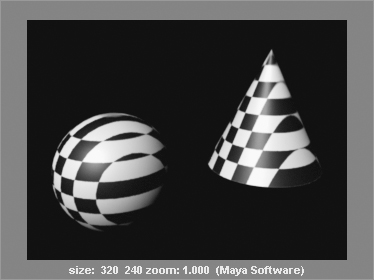
Try This In a new scene, create a NURBS sphere and a NURBS cone, and place them side by side. Create a Blinn shader, and assign it to both objects. In the Blinn shader’s Attribute Editor, set its Color attribute to a checkerboard pattern, as shown in Figure 7-31.
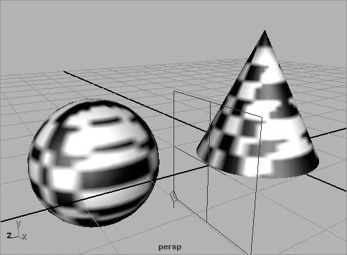
Try removing the color map from the Blinn shader. In the Blinn shader’s Attribute Editor, right-click and hold the attribute’s title word Color, and then choose Break Connection from the shortcut menu. Doing so severs the connection to the checker and resets the color to gray. Now, re-create a new checker map for the color, but this time create it as a projection by right-clicking the icon in the Create Render Node window. In the illustration on the left in Figure 7-32, you see the perspective view in Texture mode (press the 6 key) with the two objects and the planar projection placement node.
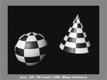
Try moving the planar placement object around in the scene to see how the texture maps itself to the objects. Figure 7-32 on the right shows the rendered objects.
Try the other projection types to see how they affect the texture being mapped.
Projection placement nodes control how the projection maps its image or texture onto the surface. Using a NURBS sphere with a spherical projected checker, with U and V wrap turned off on the checker texture, you can see how manipulating the place3dTexture node affects the texture.
In addition to the Move, Rotate, and Scale tools, you can use the Special Manipulator tool (press T to activate or click the Show Manipulator Tool icon in the toolbar) to adjust the placement. Figure 7-33 shows this tool for a spherical projection.
Figure 7-33: The spherical projection’s Manipulator tool

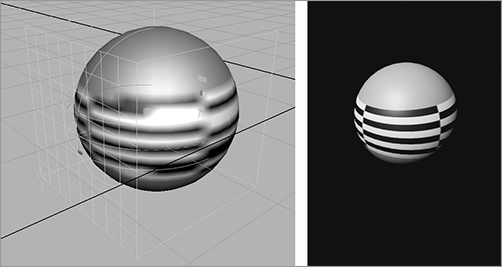
Drag the handles on the special manipulator to change the coverage of the projection, orientation, size, and so forth. All projection types have special manipulators. Figure 7-34 shows the special manipulator wrapping the checker in a thin band all the way around the sphere.
To summarize, projection textures depend on a projector node to position the texture onto the geometry.
Figure 7-34: The manipulator wrapping the Checker texture around the sphere (left, perspective view; right, rendered view)
Texture Nodes
Figure 7-35: Some common attributes for all texture nodes
You can create a number of texture nodes in Maya. This section covers the most important. All texture nodes, however, have common attributes that affect their final look. Open the Attribute Editor for any texture node. (See Figure 7-35.) The two top sections affect the color balance of the texture. The Color Balance and Effects sections are described here:
Color Balance This set of attributes adjusts the overall brightness and color balance of your texture. Use these attributes to tint or brighten a texture without having to change all the individual attributes of the shader.
Effects You can invert the texture’s color space by clicking the Invert check box. This changes black to white and white to black in addition to inverting the RGB values of colors.
You can map textures to almost any shader attribute for detail. Even the tiniest amount of texture on a surface’s bump, specular, or color increases its realism.
Place2dTexture Nodes
The 2D texture nodes come with a 2D placement node that controls their repetition, rotation, size, offset, and so on. Adjust the setting in this node of your 2D texture in the Attribute Editor, as shown in Figure 7-36, to position it within the Shader network. You used a similar approach when dealing with the wood’s 3D placement node in the axe exercise earlier in this chapter.
Figure 7-36: A 2D placement node in the Attribute Editor
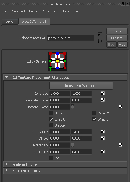
The Repeat UV setting controls how many times the texture is repeated on whatever shader attribute it’s connected to, such as Color. The higher the wrap values, the smaller the texture appears but the more times it appears on the surface.
The Wrap U and Wrap V check boxes allow the texture to wrap around the edges of their limits to repeat. When these check boxes are turned off, the texture appears only once, and the rest of the surface is the color of the Default Color attribute found in the texture node.
The Mirror U and Mirror V settings allow the texture to mirror itself when it repeats. The Coverage, Translate Frame, and Rotate Frame settings control where the image is mapped. They’re useful for positioning a digital image or a scanned picture.
Ramp Texture
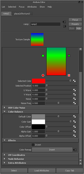
A ramp is a gradient in which one color transitions into the next color. You’ve already seen how useful a ramp can be in positioning materials in a Layered shader. It’s also perfect for making color gradients, as shown in Figure 7-37.
Figure 7-37: The Ramp texture

Use the round handles to select the color and to move it up and down the ramp. The square handle to the right deletes the color. To create a new color, click inside the ramp.
The Ramp texture is different from the Ramp shader. The Ramp shader automatically has several Ramp textures mapped to some of its attributes.
The Type setting allows you to create a gradient running along the U or V direction of the surface, as well as to make circular, radial, diagonal, and other types of gradients. The Interpolation setting controls how the colors grade from one to the next.
The U Wave and V Wave attributes let you add a squiggle to the U or V coordinate of the ramp, and the Noise and Noise Freq (frequency) attributes specify randomness for the placement of the ramp colors throughout the surface.
Using the HSV Color Noise attributes, you can specify random noise patterns of Hue, Saturation, and Value to add some interest to your texture. The HSV Noise options are great for making your shader just a bit different, to enhance its look.
Fractal, Noise, and Mountain Textures
These textures are used to create a random noise pattern to add to an object’s Color, Transparency, or any other shader attribute. For example, when creating a surface, you’ll almost always want to add a little dirt or a few surface blemishes to the shader to make the object look less CG. These textures are commonly used for creating bump maps.
Bulge, Cloth, Checker, Grid, and Water Textures
These textures help create surface features when used on a shader’s Bump Mapping attribute. Each creates an interesting pattern to add to a surface to create tactile detail, but you can also use them to create color or specular irregularities.
When used as a texture for a bump, Grid is useful for creating the spacing between tiles, Cloth is perfect for clothing, and Checker is good for rubber grips. Placing a Water texture on a slight reflection makes for a nice poolside reflection in patio furniture.
The File Node
You use the file node to import image files into Maya for texturing. For instance, if you want to texture a CG face with a digital picture of your own face, you can use the file node to import a Maya-supported image file.
Importing an Image File as a Texture
Figure 7-38: The File texture node
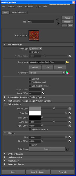
To attach an image to the Color attribute of a Lambert shader, for example, follow these steps:
1. Create the Lambert shader. (Phong, Blinn, or any of the shaders will do.)
2. Click the Map button to map a texture on the Color attribute of the new Lambert shader. Select the file node as a normal texture. (You can also use a projected texture with an image file.) The Attribute Editor shows the attribute for the file node. See Figure 7-38.
3. Next to the Image Name attribute, click the Folder icon to open the file browser. Find the image file of choice on your computer. (It’s best to put images to use as textures in the project’s Sourceimages folder. As a matter of fact, the file browser defaults directly to the Sourceimages folder of your current project.) Double-click the file to load it.
4. After you import the image file, it connects to the Color attribute of that shader and also automatically connects the alpha to transparency if there is an alpha channel in the image. You can position it as you please by using its Place2dTexture node or by manipulating the projection node if you created the File texture node as a projection.
You can attach an image file to any attribute of a shader that is mappable, meaning it’s able to accept a texture node. Frequently, image files are used for the color of a shader as well as for bump and transparency maps. You can replace the image file by double-clicking the File texture node in the Hypershade and choosing another image file with the file browser. Maya disconnects the current image file and connects the new file.
Using Photoshop Files: The PSD File Node
Maya can also use Adobe Photoshop PSD files as image files in creating shading networks. The advantage of using PSD files is that you can specify the layers within the Photoshop file for different attributes of the shader, as opposed to importing several image files to map onto each shader attribute separately. This, of course, requires a modest knowledge of Photoshop and some experience with Maya shading. As you learn how to shade with Maya, you’ll come to appreciate the enhancements inherent in using Photoshop networks.
Try This You’ll create a single Photoshop file that will shade this sphere with color as well as transparency and a bump. Again, this is instead of creating three different image files (such as TIFFs) for each of those shading attributes:
1. Create a NURBS sphere in a new scene, and assign a new Lambert shader to it. You can do this through the Hypershade or by choosing Lighting/Shading ⇒ Assign New Material ⇒ Lambert in the Rendering menu set. This creates a new shader and assigns it to the selection, in this case your sphere.
2. Select the sphere, and choose Texturing ⇒ Create PSD Network. In the option box that opens, select color, transparency, and bump from the list of attributes on the left side, and click the right arrow to move them to the Selected Attributes list on the right, as shown in Figure 7-39.
Figure 7-39: The Create PSD Network Options window

3. Select a location and filename for the image. By default, Maya places the PSD file it generates under the Sourceimages folder of your current project, named after the surface to which it applies. Click Create.
4. In Photoshop, open the newly created PSD file. You see three layers grouped under three folders named after the shader attributes you selected when creating the PSD file. There are folders for lambert2.bump, lambert2.transparency, and lambert2.color, as well as a layer called UVSnapShot.
The UVSnapShot layer gives you a wireframe layout of the UVs on the sphere as a guideline to paint your textures. Because the sphere is an easy model, you don’t need this layer, so turn it off. You’ll use UVSnapShots later in this chapter.
You can now paint whatever image you want into each of the layers to create maps for each of the shader attributes, all in one convenient file. Save the PSD file. You can save over it or create a new filename for the painted file.
5. In Maya, open the Hypershade, and open the Attribute Editor for the Lambert shader assigned to the sphere (in this case, Lambert2). If you graph the connections to the Lambert shader in the Hypershade window’s work panel, you see that the PSD file you generated is already connected to the Color, Bump, and Transparency attributes of the shader, with the proper layering set for you as shown in Figure 7-40.
Figure 7-40: The PSD network for the Lambert shader in the Hypershade shows the connections to Color, Bump, and Transparency.

6. Open the file nodes for the shader, and replace the PSD file with your new painted PSD file. If you saved your PSD file with the same name, all you need to do is click the Reload button to update the psdFilenode.
If you decide that you need another attribute added to the PSD file’s layering, or if you need to remove an attribute, you can edit the PSD network. Select the shader in the Hypershade, and choose Edit ⇒ Edit PSD Network. In the Options window, you can select new attributes to assign to the PSD file, or you can remove existing attributes and their corresponding Photoshop layer groups. When you click Apply or Edit, Maya saves over the PSD file with the new layout.
3D and Environment Textures
As you saw earlier with the axe, 3D textures are projected within a 3D space. These textures are great for objects that need to reflect an environment, for example.
Instead of simply applying the texture to the plane of the surface as 2D textures do, 3D textures create an area in which the shader is affected. As an object moves through a scene with a 3D placement node, its shader looks as if it swims, unless that placement node is parented or constrained to that object, as you saw with the wooden handle of the axe. (For more on constraints, see Chapter 9, “More Animation!”)
Disconnecting a Texture
Figure 7-41: Right-clicking a shader’s attribute allows you to disconnect a texture node from the shader.

Sometimes, the texture you’ve applied to an object isn’t what you want, and you need to remove it from the shader. To do so, double-click the shader in the Hypershade to open its Attribute Editor.
You can then disconnect an image file or any other texture node from the shader’s attribute by right-clicking the attribute’s name in the Attribute Editor and choosing Break Connection from the context menu, as shown in Figure 7-41.