Application: Rigging the Locomotive
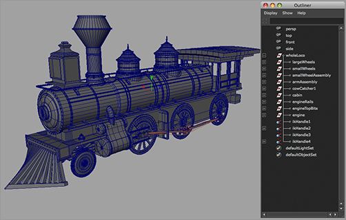
Let’s get back to our locomotive. In the previous chapter, you made sure the hierarchy and pivot placements were proper. In this exercise, you can use your own locomotive scene or the locomotive_anim_v1.mb file from the previous chapter. You can also use a fancy version of the locomotive, called fancy_locomotive_anim_v1.mb; it’s set up similarly to locomotive_anim_v1.mb for the exercise. This scene is shown in Figure 9-63.
Familiarize yourself with the scene file first. To give yourself more modeling practice, you can use this scene file to remodel your own fancy locomotive if you like. All the parts of this fancy locomotive were made using the basic tools and procedures laid out in Chapter 4, “Beginning Polygonal Modeling.”
Figure 9-63: The fancier locomotive model

Setting Up Wheel Control
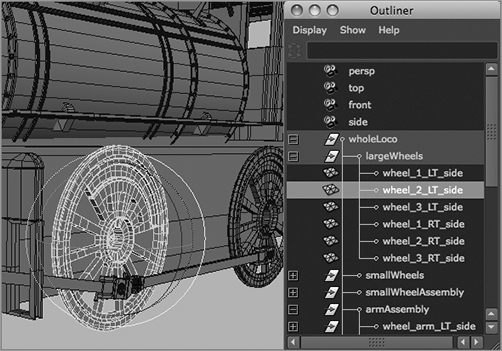
Figure 9-64: Select the middle wheel.
Your goal here is to rig the scene to animate all the secondary movements automatically based on some simple controls, such as you did for the hand earlier this chapter. In reality, the locomotive’s steam pump drives the arms that then turn the wheels on the locomotive. You’ll work backward, however, and use one wheel to drive the animation of everything else.
Because all the large wheels have the same diameter, they rotate the same as the locomotive moves. In this case, you’ll use the Connection Editor to attach the X Rotation on all the wheels to your main control wheel. You’ll pick the middle wheel to be the control. To set up the locomotive, follow these steps:
1. Select the middle wheel on the left side of the locomotive (node wheel_2_LT_side), as shown in Figure 9-64. Open the Connection Editor (choose Window ⇒ General Editors ⇒ Connection Editor). Click the Reload Left button to load the attributes of the selected middle wheel. Now, select the front wheel on the left side, and click the Reload Right button.
Figure 9-65: Connect the rotations of the two wheels.

2. Scroll down in the Connection Editor until you find Rotate in both columns. Click to highlight Rotate in the left column, and then click to highlight Rotate in the right column. Doing so connects the two rotations so that they both rotate at the same time, effectively letting you drive the animation of both wheels from just the center wheel. Figure 9-65 shows the Connection Editor.
3. Select the back wheel on the left side (wheel_3_LT_side). Click the Reload Right button in the Connection Editor. Connect the Rotate attribute for the middle and the back wheels. Close the Connection Editor, and select just the middle wheel. When you rotate the wheel, all three wheels rotate together.
4. Repeat this procedure to connect the rotations of the three wheels on the other side to this middle wheel as well. Now all six wheels rotate in synch with the one control wheel. When you select that left-side middle wheel (the control wheel), the other five wheels turn magenta, signifying a connection between these objects.
If you get strange results when you connect the rotations of objects (for example, if the wheels flip over or rotate the opposite direction of the control wheel), try disconnecting all the connections, freezing transforms, and reconnecting the attributes.
Controlling the Wheel Arms
You’ve now automated the animation of the wheels. Next, you’ll figure out how to connect the wheel arms to the wheels and drive their motion as well. To do so, follow these steps:
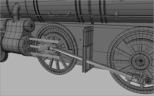
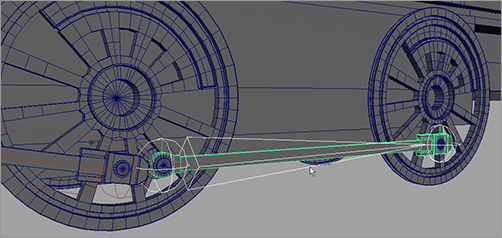
1. Create a single joint that lines up with the first wheel arm. The root joint is placed where the wheel arm meets the middle wheel (control wheel), and the end joint is placed where the wheel arm meets the pump arm, as shown in Figure 9-66. The pump arm has been templated in this graphic (displays in light gray wireframe) to show you the entire wheel arm and joint.
Figure 9-66: Create a joint from the middle wheel to the pump arm at the first wheel.
2. Group the joint under the control wheel’s node, as shown in the Outliner in Figure 9-67. Then, group the wheel arm under the top joint. This way, the joint rotates with the control wheel, also shown in Figure 9-67, albeit incorrectly for the pump arm.
3. As you saw in Figure 9-67, the joint isn’t rotating properly to make the pump arm work right. The other end of it needs to attach to the pump arm in front of the front wheel, not fly up in space. You can use an IK handle for this. Make sure the rotation of the control wheel and the joint/wheel arm are set back to 0 to place them in the original position. In the Animation menu, choose Skeleton ⇒ IK Handle Tool. Make sure the settings are reset for the tool. Select the root joint as the start joint for the IK Handle. Select the other tip of the bone as the end effector. You now have an IK handle at the tip where the wheel arm connects to the pump arm, as shown in Figure 9-68.
Figure 9-67: Group the top joint under the wheel, and then group the wheel arm under the top joint.
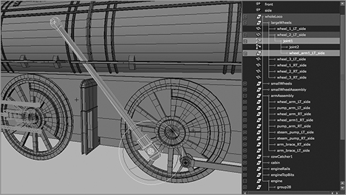
Figure 9-68: Place the end effector where the pump arm and the first wheel connect.

Figure 9-69: Group the IK handle under the locomotive’s top node.

4. If you rotate the control wheel now, the wheel arm still separates from the pump arm. This is because the IK handle you just created needs a keyframe to keep it in position—that is, attached to the pump arm. Select the IK handle, and, at frame 1, set a position keyframe. Now, if you rotate the control wheel, the joint and wheel arm pump back and forth.
5. Group the IK handle (ikHandle1) under the top node of the locomotive (wholeLoco), as shown in Figure 9-69.
Controlling the Pump Arm
Next, you need to attach the pump arm to the wheel arm so that it pumps back and forth as the control wheel turns. If you simply group the pump arm with the end joint of the wheel arm’s bone, the pump arm will float up and down as it pumps back and forth. You need to use a constraint to force the pump arm to move back and forth only in the Z-axis:
1. Make sure the control wheel is set back to 0 rotation. Select the pump arm, templated in Figure 9-70 so that you can see through to the wheel arm and joint, and line up its pivot with the end joint of the wheel arm bone.
2. Select the end joint (called joint2), Ctrl+click the pump arm group in the Outliner (called pump_arm_LT_side), and, in the Animation menu, choose Constrain ⇒ Point ❒. In the option box, uncheck All under Constraint Axes, select only Z to constrain the pump arm only in the Z-axis, and click the Add button. Now, if you rotate the control wheel, you see the pump arm and wheel arm connected. The pump arm pumps back and forth, although you’ll immediately notice a need to adjust the model to make the piece fit when it animates. Figure 9-71 shows that the pump arm’s geometry isn’t yet quite right for animation. This is very normal for this process and luckily needs only a quick fix.
Figure 9-70: Line up the pivot of the pump arm with the end joint of the wheel arm joint.
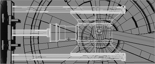
Figure 9-71: The pump arm is too short!
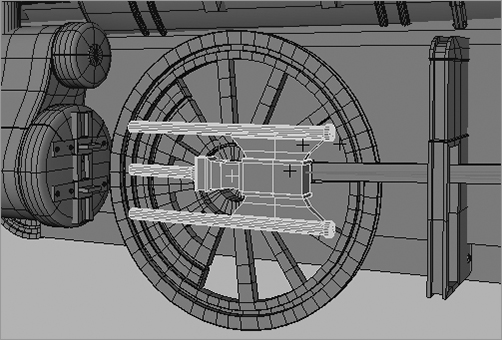
Figure 9-72: Use vertices to extend the pump arm.

3. To fix the pump arm, select the vertices on the ends of the cylinders, and extend them to make them longer, as shown in Figure 9-72. Now the pump arm won’t pull out of the steam pump assembly.
4. Adjust the pump arm so that the geometry fits when the pump pushes in as well.
The scene file fancy_locomotive_anim_v2.mb will catch you up to this point. Compare it to your work.
Controlling the Back Wheel
All that remains is to control the animation of the back wheel and its wheel arm. To set up the wheel arm animation, follow these steps:
1. Using the methods described in the steps in the “Controlling the Wheel Arms” section, create a joint to follow along the wheel arm between the middle control wheel and the back wheel. The root of the joint is set at the control wheel, as shown in Figure 9-73.
Figure 9-73: Create a joint to control the back wheel arm.
2. As before, create an IK handle for the end joint of this new bone, where it meets the back wheel, as shown in Figure 9-74. Make sure the handle is at the back wheel, not the middle control wheel.
3. Group the new joint under the master wheel, and then group the wheel arm under this new joint. If you rotate the control wheel, the wheel arm rotates with the joint and wheel but doesn’t connect to the back wheel yet. You need to attach the IK handle you just created for that joint to the back wheel.
Figure 9-74: Create an IK handle to attach the wheel arm and the back wheel to the control wheel.
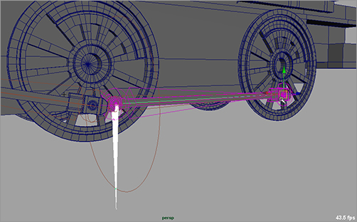
If you group the IK handle, as shown in Figure 9-75, you’ll run into a problem when you animate. Let’s try it: Group the IK handle (ikHandle2) under the end back wheel, as shown in Figure 9-75, and then rotate the control wheel. The wheel arm pumps back and forth along with the back wheel, but every now and then the wheel arm geometry flips over backward. This isn’t good.
Fixing this is easy. The grouping of the IK handle to the back wheel is causing the issue. Although that is pretty much what you want to do, parenting the IK handle under the wheel is problematic. Here is where the parent constraint becomes extremely helpful. It gives you the desired result without the geometry flipping.
Figure 9-75: The wheel arm geometry flips over if you group the IK handle under the back wheel.

4. Make sure your control wheel is back to 0 rotation first. MMB+click in the Outliner, and place the IK handle outside the hierarchy of the locomotive to remove the IK handle from under the back wheel’s node. You may also undo your past actions to the point before you grouped the IK handle (ikHandle2) under the back wheel. You gotta love Undo.
5. Select the back wheel, Shift+click the IK handle (ikHandle2), and choose Constrain ⇒ Parent. Now, if you rotate the control wheel, everything works great.
6. Group the IK Handle (ikHandle2) under the top node of the locomotive (wholeLoco).
You can use fancy_locomotive_anim_v3.mb to compare your work.
Again, seeing procedures go slightly awry, as when the wheel arm flipped over, is important. Doing so gives you a taste of trouble and a chance to fix it. Troubleshooting is an integral skill for a good CG artist.
Finishing the Rig
You’re almost home free with the locomotive wheel rigging. Everything works great when you rotate the control wheel. If you select the top node of the locomotive and translate the train back and forth, everything should work perfectly. Repeat the steps in the previous few sections to connect the wheel arms and wheels on the other side of the locomotive, and you’re finished! Figure 9-76 shows the completed and rigged locomotive.
Figure 9-76: The rigged fancy locomotive