
In your body, your muscles move your bones; and as your bones move, parts of your body move. Bones are your internal framework.
In CG animation, a skeleton is an armature built into a 3D model that drives the geometry when the bones are moved. You insert a skeleton into a CG model and attach or bind it to the geometry. The skeleton’s bones are animated (typically with rotations), which in turn move the parts of the geometry to which they’re attached. By using a skeleton, Maya allows bending and deformation of the attached geometry at the skeleton’s joints. A skeleton is, of course, useful for character work, but skeletons have many other uses. Any time you need to drive the geometry of a model with an internal system, such as fly-fishing line or a tree bending in the wind, you can use skeletons. You’ll use them to drive the locomotive later in this chapter.
Skeletons and Hierarchy
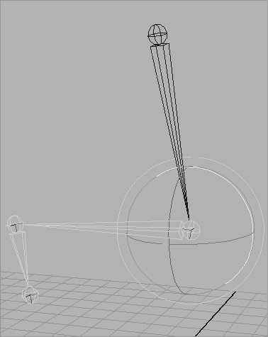
Figure 9-1: A leg skeleton and its hierarchy

Skeletons rely on hierarchies. Bones are created in a hierarchical manner, resulting in a root joint that is the parent of all the joints beneath it in the hierarchy. For example, a hip joint can be the root joint of a leg skeleton system in which the knee joint is the leg’s child, the ankle joint belongs to the knee, and the five toe joints are the ankle’s children. (See Figure 9-1.)
Using skeletons, you can easily create an immediate hierarchical system with which to animate. Furthermore, pieces of geometry need not deform to be attached to a bone system. Objects can be grouped with or under joints. They move under their parent joint and rotate around that joint’s pivot as opposed to their own pivot point.
A skeleton is really just a collection of grouped and properly positioned pivot points called joints that you use to move your geometry, whether it deforms or not. A bone is the length between each joint; bones only show you the skeletal system.
Inverse Kinematics (IK) and Forward Kinematics (FK) are the methods you use to animate a skeletal system. FK rotates the bones directly at their top joint to assume poses. This method resembles stop-motion animation, in which a puppet, along with its underlying armature, is posed frame by frame. With FK, the animator moves the character into position by rotating the joints that run the geometry.
Figure 9-2: In Forward Kinematics, the joints are rotated directly.
The rotation of a joint affects the position of the bones and joints beneath it in the hierarchy (see Figure 9-2). If you rotate the hip up, the knee and ankle swing up as if the character is kicking. If you rotate the knee down, the ankle pivots down as if this character is seated. This form of motion moves the way you would expect it to move in hierarchies and is, therefore, called Forward Kinematics.
IK uses a more complex, but often easier, system of IK handles that are attached to the tip of a joint system. The corresponding base of the IK system is attached further up the skeleton hierarchy to a joint determined to be the root of that IK segment. It need not be the root joint of the entire skeleton, though.
Figure 9-3: In Inverse Kinematics, the joints rotate in response to the IK handle’s position.

The bones and joints in the IK chain are affected only by movement of the IK handle. When the handle moves, an IK solver figures out how to rotate all the joints to accommodate the new position of the IK handle. Moving an IK handle causes the bones to rotate around their joints to accommodate a new position.
The effect is as if someone grabbed your hand and moved it. The person holding your hand is similar to an IK handle. Moving your hand causes the bones in your arm to rotate around the shoulder, elbow, and wrist. As you can see in Figure 9-3, the animation flows up the hierarchy and is, therefore, called Inverse Kinematics.
Forward Kinematics: The Block Man
To understand skeletal hierarchy, look at the simple biped (two-legged) character made of primitive blocks, shown in Figure 9-4. He’s called Block Man. (Surprise!) Each block represents a part of the body, with gaps between the blocks representing points where the body pivots.
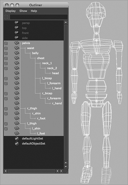
Figure 9-4: The block man’s cubes arranged

The pivot of each block is placed to represent the appropriate joint location. For example, the shin’s pivot is located at the knee. Each block is grouped up the chain so that the foot moves with the shin, which moves with the thigh, which moves with the pelvis.
The hands are grouped under the arms, which are grouped under the shoulders, and so forth down the spine to the pelvis. The head groups under the first neck block, and so on down the spine to the pelvis. The pelvis is the center of the body, which is known as the root of the figure.
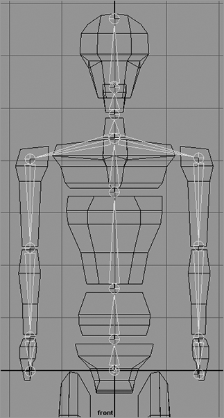
The way this figure is grouped (see Figure 9-5) represents how the hierarchy of a character works for the most part. Each body part is attached and becomes the child of the part above it in the chain.
Figure 9-5: Pivot placements and grouping
Load the file block_man_v02.mb from the Block_Man project folder on the CD for a good reference of the grouping structure. This file shows you what a skeleton hierarchy does.
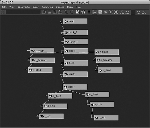
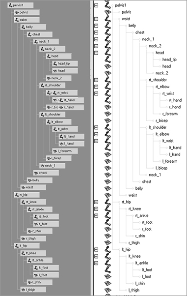
In the Hypergraph Hierarchy window, choose Options ⇒ Layout ⇒ Freeform Layout to position the nodes any way you want. To make selections easier, you can arrange the nodes as if they were on a body (see Figure 9-6). You can toggle between freeform and automatic, and your freeform layout will be retained.
Figure 9-6: A freeform layout in the Hypergraph Hierarchy window
Creating the Skeleton
The basis of how the block man is laid out and grouped is what skeletons are all about. Skeletons make character animation easier by automating, at the very least, the hierarchy and pivot placement described earlier.
The Pelvis as Root
Traditionally, the pelvis is the basis of all biped setups. The root of any skeletal system (whether using bones or geometry as the example) is the character’s pivot point—the center of balance. Because a biped character centers itself on two feet, its pelvis becomes the root of its skeletal system. In CG, the pelvis becomes the parent node of the whole system and is the node used to move or orient the entire character. In a skeleton system, this would be the root joint.
The root is then the top parent of the system below it and runs the entire chain. Therefore, selecting character parts straight from the Outliner or the Hypergraph is sometimes easier. You can see that a good naming convention is always important with character setups.
You’ll use the block man to create a skeleton. Load block_man_v01.mb from the Block_Man project. This is the same as block_man_v02.mb, but this version isn’t grouped.
1. Maximize the Front view window. Switch to the Animation menu by using the drop-down menu or by pressing F2.
2. Activate the Joint tool by choosing Skeleton ⇒ Joint Tool. Your cursor turns into a cross.
3. Click in the middle of the pelvis to place the first joint, the root joint of the skeleton.
4. Shift+click up to the space between the pelvis and the waist.
The joint display sizes in your Maya window may not match those shown in the book. This isn’t a problem; however, you can change the joint sizes by clicking Display ⇒ Animation ⇒ Joint Size.
Figure 9-7: Place spine joints straight up the middle of the body.

By pressing Shift as you click, you create a joint in a straight line from the last joint placement. A bone is created between the two joints as a visual guide to the skeleton. The placement of the joints depends on the active view, so placing a second joint in a different view may place the joint in an awkward location.
5. Click more joints up the spine at the gaps between the body parts, as shown in Figure 9-7.
6. You need to start a new branch of joints leading into the legs and arms. Begin with the arms. With the Joint tool still active, press the Up arrow key three times to move up the hierarchy of joints to the one between the neck and chest parts.
Pressing the Up arrow key takes you up one node in a hierarchy. Pressing the Down arrow key takes you down one node in a hierarchy. This approach also applies to skeletons, because they’re hierarchies.
Figure 9-8: Place joints for the torso.
7. Stay in the front view. Now, from this joint between the neck and chest, click to place a joint at the top of the right bicep at the shoulder. Click down to create joints at the elbow, the wrist, and the tip of the model’s right hand.
8. Press the Up arrow to pick walk up the chain to the neck/chest joint, and repeat step 7 to create the joints for the left arm as shown in Figure 9-8.
Pick walking is when you select one object or component in Maya and then use the Up or Down arrow key to pick the next object higher (or lower) in the hierarchy. You can use the Left or Right arrow key to pick-walk select any siblings of the currently selected object in its hierarchy.
9. To start another string of joints in the first leg, pick walk back up the skeleton until you’re at the pelvis root joint. (See Figure 9-9.)
10. From the root joint at the pelvis, click to create a joint at the tip of the right thigh, and work down to the knee and ankle. Place the ankle joint halfway down the foot, as shown in Figure 9-10, as opposed to the gap between the shin and the foot. Press the spacebar to return to the four-way view from the front view, and maximize the side view. Click to create a joint at the tip of the foot. This allows you to place a joint in the proper axis in the side view. (See Figure 9-11.)
11. Return to the front view, and press the Up arrow to get back to the pelvis joint. Repeat step 10 to create joints for the left leg. After you place your joints, press Enter. Figure 9-12 shows the skeleton.
Figure 9-9: Start the leg series of joints from the root pelvis joint.

Figure 9-10: Place a joint inside the foot, not in the gap between the foot and the shin.

Figure 9-11: In the Side view panel, create a joint at the tip of the foot.
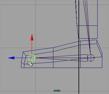
Figure 9-12: The full skeleton for the block man

Attaching to the Skeleton
Figure 9-13: Use a consistent naming scheme for the joints to make it easy to keep track of them.

You now have a full skeleton for your character. To attach the geometry, all you need to do is parent the body parts under their appropriate joints. Before you get to that, take a few minutes and name all the joints in the Outliner to make the scene easier to manage. Figure 9-13 shows the names used in the project on the CD.
You can also load the block_man_skeleton_v01.mb file from the Block_Man project to get to this point.
To parent the block man’s geometry to the skeleton, follow these steps:
1. Starting with the right foot, parent it under the right ankle joint (rt_ankle) by MMB+clicking and dragging it to rt_ankle in the Outliner or the Hypergraph. You don’t want to parent it under the right foot joint (rt_foot), because you need the foot geometry to pivot with that foot bone and inherit the rotations from the ankle above it. Parent the left foot under the left ankle (lt_ankle). (See Figure 9-14.)
Figure 9-14: Begin organizing the hierarchy by grouping the block man’s parts into the skeleton.

Figure 9-15: Views of the skeleton and geometry hierarchy in the Outliner and the Hypergraph
2. Parent the rest of the body parts (see the following list) under their respective joints, as shown in Figure 9-15:
- Shins under the knees, and thighs under the hips
- Hands under the wrists, and forearms under the elbows
- Biceps under the shoulders
- Head under the head joint (the joint between the head and the top neck geometry)
- Top neck geometry under the joint between the two neck pieces
- Bottom neck geometry under the joint between the chest and the neck
- Chest under the joint between the chest and belly pieces
- Belly under the joint between the belly and waist
- Pelvis with the root joint
The Block Man: Walk Cycle
A walk cycle is an animation that takes the character through a few steps that can be repeated many times so that the character seems to be taking numerous steps. In a cycle, make sure the position of the first frame matches the position of the last frame so that when the animation sequence is cycled, no “pop” occurs in the motion at that point.
Now, try animating this character’s walk cycle using FK on the skeleton. You’ll find the workflow straightforward, as if you were adjusting positions on a doll.
Load the block_man_skeleton_v02.mb file from the Block_Man project on the CD for the properly grouped model and skeleton.
Use the key poses in the following figures to guide you in animating the body as it walks. You’ll key at five-frame intervals to lay down the gross animation. You can go back and adjust the timing of the joint rotations in the Graph Editor to make the animation better. The white leg and arm are behind the body, farther from the camera.
This animation is also called pose animation because you’re posing the character from keyframe to keyframe.
Starting Out: Frames 1 and 5
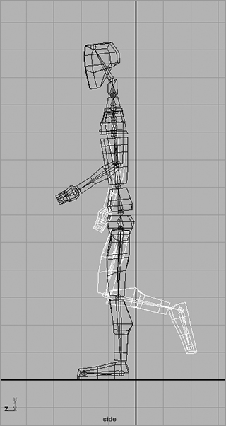
Figure 9-16 shows the character’s starting position. Here you’ll set a key for this position and then begin the walk cycle by moving the joints into their second position and keyframing that:
Figure 9-16: The character’s starting position

1. At frame 1, set a key for the rotation of all the joints. The easiest way is to select all the joints in the Outliner or the Hypergraph. With this pose animation, make sure all the joints are keyframed at every step, even if Auto Keyframe is turned on. Also set a position keyframe for just the pelvis joint.
A quick way to select all the joints, and only the joints, is to filter the Outliner view to show only joints. In the Outliner, choose Show ⇒ Objects ⇒ Joints. To reset the Outliner, choose Show ⇒ Show All.
2. Go to frame 5. Rotate the back leg (the block man’s right, white leg) back, and rotate the foot to make it level again. Lower the body (select and move the pelvis joint) to line up the back heel with the ground. This will keep the man on the ground as he goes through the walk cycle, although he won’t actually move forward yet.
3. Rotate the near leg (the man’s left leg) forward, bend the knee, and pivot the foot up a bit.
4. Rotate the back arm forward, and rotate the near arm back (opposite from the legs). Bend the arms at the elbows.
5. Bend the man forward at the waist, bend neck_1 forward, and tilt the head back up to compensate a little. Figure 9-17 shows the pose at this point.
Figure 9-17: The second pose (frame 5)

6. Select everything in the Outliner, and set a rotation key. You’re setting a pose for all the joints, which will ensure that all the body parts are in synch.
If you don’t key everything every step of the way, some parts of the body won’t key with Auto Keyframe properly because the last time they moved may have been two steps previous.
Frame 10
Figure 9-18 shows the position you’ll keyframe at frame 10; it’s approximately midstride for the first leg:
Figure 9-18: The third pose (frame 10)

1. Go to frame 10. Rotate the back leg out farther, and level the foot. Lower the body to place the man on the ground.
2. Rotate the front leg out, straighten the knee, and flatten the foot to place it on the ground. This is midstride. Swing the arms in their current direction a touch more. Bend the torso forward some more. Make sure you set a key for all the joints.
Frame 15
Figure 9-19 shows the position you’ll keyframe at frame 15. At this point, the character begins to shift his weight to the front leg as it plants on the ground, and the character also begins lifting the back leg:
1. Go to frame 15. Rotate the front leg back toward the body, and raise the body as the man steps to keep the front foot flat on the ground. Rotate the back knee up to lift the foot, and rotate the foot down to make him push off the toe.
2. Start swinging the arms in the opposite direction. Start straightening the torso back up, but bend the head forward a bit.
Figure 9-19: The fourth pose (frame 15)

Figure 9-20: The fifth pose (frame 20)
Frame 20
At frame 20, the man will shift all his weight onto the front leg and move his body over that leg, lifting his rear leg to begin its swing out front to finish the stride. Figure 9-20 shows the pose. Follow these steps:
1. Rotate the front leg almost straight under the man, and lift up the body to keep the front foot on the ground. Lift the rear leg, and swing it forward.
2. Straighten the torso, and keep the arms swinging in their new direction. Key all the joints.
Frame 25
Now, the man will swing his whole body forward, pivoting on the left leg (the dark one) to put himself off center and ready to fall forward into the next step. Figure 9-21 shows the pose. Here are the steps:
1. Go to frame 25.
Figure 9-21: The sixth pose (frame 25)

2. Rotate the front (dark) leg back behind the man, and swing the white leg up and ready to take the next step. Lower the body to keep the now rear foot (the dark one) on the ground.
Frame 30
Use Figure 9-22 as a guide for creating the next pose. Notice that it’s similar to the pose at frame 10 (in Figure 9-18). As a matter of fact, the only major differences are which leg and arm are in front. Everything else should be about the same. You’ll want some variety in the exact positions to make the animation more interesting, but the poses are very similar.
Figure 9-22: The seventh pose (frame 30)

Completing the Cycle
You’ve finished a set of poses for the character’s first step. The next set of poses for your walk cycle corresponds to the first set, but now the other leg and arm correspond to these positions. For example, you animated the left leg taking a step forward in the first series of poses. The next series of poses has to do with the right leg. The pose at frame 35 corresponds to the pose at frame 15. Frame 40 matches frame 20. You can start a new series of poses with the left leg.
When a 30-frame section is complete, you need to return to the animation through the Graph Editor. Adjust all the keyframes that you set at five-frame intervals to make the animation more realistic. Right now, you have only the gross keyframes in place, so the timing is off. Your next step is to time the frames properly. This is ultimately a matter of how the animation looks to you.
Logistically speaking, some poses take a little less time to achieve than the evenly spaced five frames you used. For example, achieving the second pose from the start position should take four frames. The third pose (see Figure 9-18, earlier in the chapter) from frame 5 to frame 10 should take four frames. The next frame section, originally from frame 10 to 15 (the fourth pose; see Figure 9-19, earlier in the chapter), should take only three frames. To accomplish this easily, follow these steps:
1. Select the top node of the skeleton (the pelvis), and open the Graph Editor. On the pelvis node in the left side of the Graph Editor, Shift+click the plus sign to open the entire tree of nodes beneath the pelvis. All the animated channels show their curves to the right, as shown in Figure 9-23.
Figure 9-23: The Graph Editor shows the walk cycle animation curves.

2. Marquee-select all the keyframes on the curves beyond frame 1, but not including those at frame 1. Press the W key to activate the Translate tool. Shift+MMB+click in the Graph Editor (so you can move only in one axis), and drag the keys horizontally to move them all 1 unit (frame) to the left. All the keyframes move, and the second pose now goes from frame 5 to frame 4.
3. Deselect the keys now at frame 4 by holding down the Ctrl key (you also use the Ctrl key on a Mac) and marquee-deselecting all those keys at frame 4. Shift+MMB+click, and drag the remaining selected keys 1 unit to the left again. The third pose goes from being at frame 9 to frame 8.
4. Deselect the keys now at frame 8, and Shift+click and drag the other selected keys to the left two frames so that the fourth pose animates between frame 8 and frame 11. Deselect the frame 11 keys, and move the rest over two frames to the left again so that the next section runs from frame 11 to frame 14. The following section should go from frame 14 to frame 18. The final section should go from frame 18 to frame 22. Figure 9-24 shows the new layout for the curves.
5. Continue to set and adjust keys for another cycle or two of the walk. The majority of time spent in animating something like this involves using the Graph Editor to time out the keyframes to make the animation look believable. Also try offsetting some of the arm rotations a frame to the left or right to break up the monotony that arises from having everything keyed on the same frame.
Figure 9-24: The keyframes are repositioned.

Load the file block_walk_v01.mov or block_walk_v01.avi of this walk cycle from the Images folder of the Block_Man project on the CD to see the animation in motion. It’s a rough cycle, and you have to keep adjusting the character’s height to keep the feet on the ground. This is where IK comes in handy, as you’ll see later in this chapter. Also, the file block_man_skeleton_walk_v01.mb in the Block_Man project has the keyframed cycle for you to play with and continue animating.
Walk Cycle Wrap-Up
This walk cycle animation is more about getting comfortable with keyframing and skeletons than it is about creating great walk cycles, so take some time to practice and get better. Animating walk cycles is a good way to hone your animation skills. Several great books are devoted to character rigging and animation alone, and you can research the field for ways to become more proficient. But keep in mind that movement and timing are what make animation good, not the setup or the model.