
Remember Figure 6-17? Take a peek at that figure again; I’ll wait. You’ll see that all that remains to do for your model are the wood railings placed around the four sides of the wagon.
Figure 6-104: Create a cube, and position it to be the top rail on the side of the wagon.

These models will be pretty simple; they’re all based on poly cubes with some slight alterations to round a corner here or there. To start modeling the rails, begin with these steps:
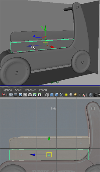
1. Switch back to the Polygons menu set. In the Side view panel, create a poly cube; use the side and front reference planes to scale and place the cube to fit the top rail on the side, as shown in Figure 6-104. Again, use the side reference view primarily to position the railing, because the front and top view will be a little off due to perspective in the photos.
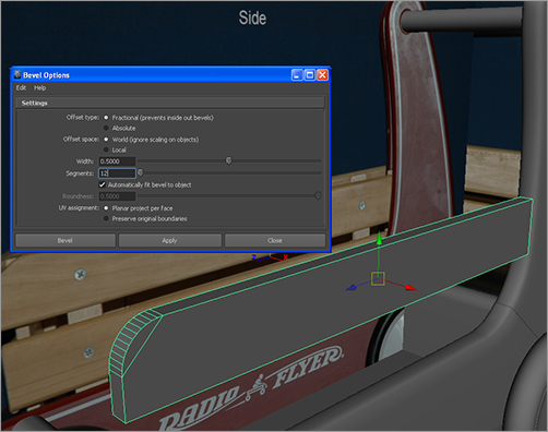
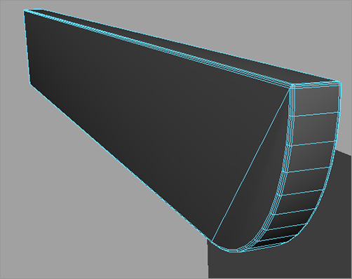
2. To round the one corner of the railing, select the top edge at the end to be rounded and choose Edit Mesh ⇒ Bevel ❒. Reset your Bevel settings by selecting Edit ⇒ Reset Settings in the Options box. Set Segments to 12, and bevel that edge. See Figure 6-105.
Figure 6-105: Bevel the end of the rail.
3. It’s unseemly to leave the rest of the edges of the mesh sharp. Adding a slight bevel to the edges will enhance the look and fidelity of the railings in your model. Especially when you begin lighting, beveled edges and corners are much nicer than perfectly sharp edges and corners, even if it’s a small bevel. Select the outer edges that run all the way around the cube, as shown in Figure 6-106.
4. Set the Bevel options to a Width of 0.25 and Segments of 3, and bevel those outer edges, as shown in Figure 6-107.
Figure 6-106: Select the outer edges, but not the inner edges.

Figure 6-107: Put a slight bevel around the railing.

5. Delete the history from the top railing, and freeze its transforms (Modify ⇒ Freeze Transformations).
6. Create another cube. Scale and position it as the bottom rail under the one you just created. See Figure 6-108.
Figure 6-108: Place a second cube for the bottom railing.
7. You need to bevel the end of the bottom railing to match the real railing on the wagon. But the cube is resting inside the wagon mesh right now, because you already lined it up perfectly. The easiest thing to do here is to freeze transforms on the cube so its position values reset to 0,0,0 in X, Y, Z space.
8. Move the cube out of the way of the wagon, anywhere in the scene you’d like. I suggest you move it just above the wagon so you can see the obscured end more easily, as shown in Figure 6-109.
9. Select the bottom edge at the right end of the cube, as shown in Figure 6-110.
10. Set your Bevel options to Width 1.0 and Segments 12, and bevel that end, as shown in Figure 6-111.
Figure 6-109: After you freeze transformations, move the cube to a better space in which to work.
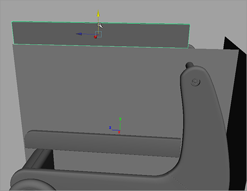
Figure 6-110: Select the bottom edge on the right end of the cube to round that end.
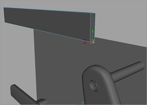
Figure 6-111: Bevel the end to round it out.

11. While the object is still clear of the wagon, bevel the outside edges as you did on the other railing. Select all the outer edges, being careful not to select the inner edges, and bevel them with Width 0.25 and Segments 3, as before. See Figure 6-112.
Figure 6-112: Bevel the rest of the edges.
12. What good is the railing if it’s nowhere near the wagon? That’s easy to fix. Earlier, you froze its transforms so that, in its proper place, the railing was at location (0,0,0) in 3D space. Therefore, you can enter those values in the Channel Box to place the railing exactly where it was before. Figure 6-113 shows the bottom railing back in place; however, it’s still cutting into the wagon. You’ll fix it in place with a lattice.
13. With the bottom railing still selected, switch to the Animation menu set (F2), and choose Create Deformers ⇒ Lattice ❒. Set Divisions to 2, 2, 2, and click Create.
14. Enter X-Ray mode in the Perspective panel (choose Shading ⇒ X-Ray in the persp panel’s menu bar). You see the lattice sticking into the wagon body, as shown in Figure 6-114.
Figure 6-113: Put the railing back.

Figure 6-114: Create a lattice.
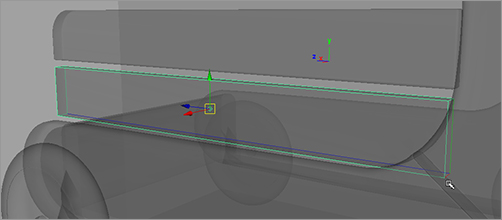
Figure 6-115: In X-Ray mode, select the bottom lattice points on the end buried in the wagon.

15. With the lattice still selected, RMB+click one of the lines of the lattice, and select Lattice Point from the marking menu. You may have to RMB+click around to get the correct marking menu that displays Lattice Point as a selection option. Try not to RMB+click the wagon itself, to avoid having the wrong marking menu appear. Select the two bottom lattice points, as shown in Figure 6-115.
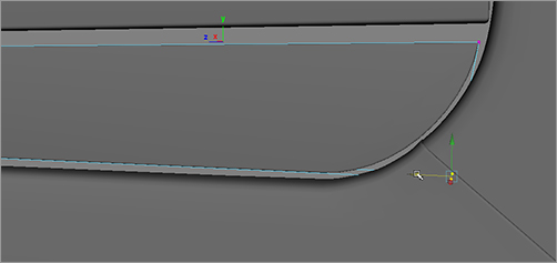
16. Exit X-Ray mode with the lattice points still selected by choosing Shading ⇒ X-Ray to toggle it off in the persp panel. Move the two lattice points to deform the bottom rail’s end properly to create a gap between the railing and the wagon, as shown in Figure 6-116.
Figure 6-116: Use the lattice to put a gap between the curved railing and the wagon.
17. Select the railing mesh object, and delete its history to remove the lattice but keep the deformation. Switch back to the Polygons menu set (F3).
18. You need to make the braces behind the railings. Create a poly cube, and then scale and position it to match the front end brace behind the railings, as shown in Figure 6-117. The brace should reach the floor of the wagon and should extend to just below the top railing edge.
19. With the cube selected and in position, choose Edit Mesh ⇒ Bevel ❒. Set Width to 0.25 and Segments to 3. This puts a slight bevel around the entire edge of the brace, as shown in Figure 6-118. Having edges beveled helps light catch the edges of an object when you light and render it, even for seemingly inconsequential parts of the model.
Figure 6-117: Place a cube as the brace behind the railings.

Figure 6-118: Bevel the brace.

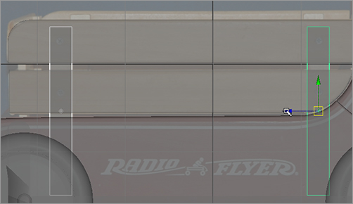
20. Duplicate the brace, and place it toward the back of the wagon according to the side reference image. See Figure 6-119.
21. Select the top rail, and name it topRail. Name the bottom rail bottomRail, and name the braces brace1 and brace2. Select all four objects (two rails and two braces), and group them together. Name the group sideRailing. Center the pivot (Modify ⇒ Center Pivot).
Figure 6-119: Duplicate and place the second brace.
22. With the sideRailing group selected, duplicate the group and move it to the other side of the wagon. Set its X scale to -1.0 to mirror it. Place it properly against the other side of the wagon, as shown in Figure 6-120. Feel free to adjust the length of the side railings to make them fit your model best; they don’t need to line up exactly to the side reference image plane. Do what looks best for your model if you find you’re deviating a bit from the reference images, which is easy to do.
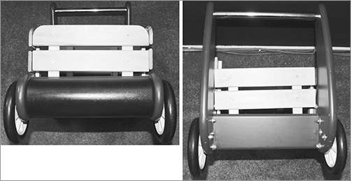
23. Use the same procedures as in the previous steps to create the front and back railings. Figure 6-121 show these railings in a more detailed photo. The front railing is shown on the left, and the back railing is shown on the right.
Figure 6-120: Duplicate, mirror, and place the other side’s railing.
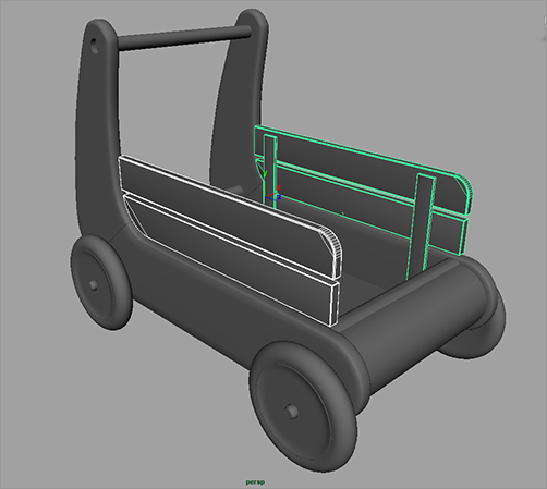
Figure 6-121: The front (left) and rear (right) railings of the wagon
24. After you’ve created the railings, make sure to name them properly. Group the front railing objects together, and name the group frontRailing. Group the objects for the rear railing together, and name that group rearRailing. Figure 6-122 shows the railings in place, and Figure 6-123 shows the Outliner view of the scene.
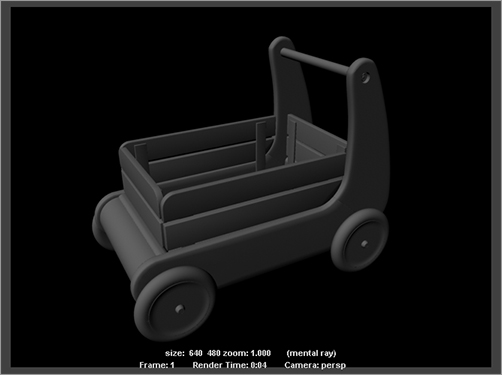
And that’s it! Save your work. The red wagon has taken shape and looks pretty good. Figure 6-124 shows the wagon in the persp panel, and Figure 6-125 shows a render of the wagon. Just wait until you render this puppy!
Figure 6-122: The railings are in place.
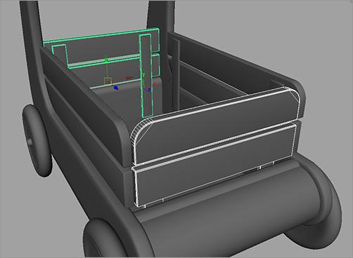
Figure 6-123: Keep everything properly named and grouped.
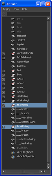
Figure 6-124: The completed wagon model
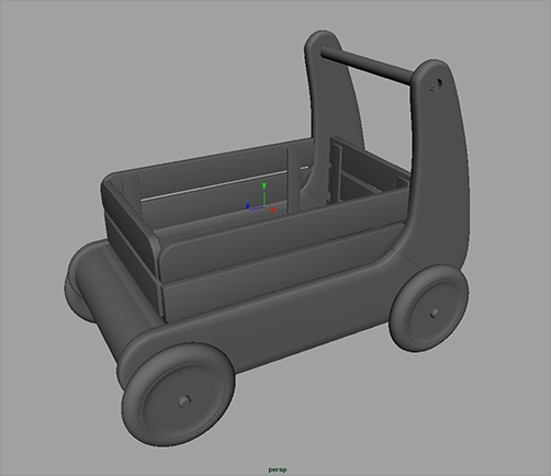
Figure 6-125: A render of the wagon!
You can load the scene file RedWagonModel_v07.ma from the Scenes folder of the RedWagon project on the CD to check your work or to skip to this point.