
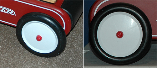
What’s a kid’s wagon without wheels? That would be no fun. How else would it smash into all your expensive stuff? You’re going to make a wheel for the wagon and then duplicate it. Figure 6-92 shows the object of your design. You’ll complete the wheel model by revolving a NURBS surface and converting it to a poly.
Figure 6-92: Ensign, take the wheel! (The author is a dork.)
Creating the Profile Curve
You’ll begin the first wheel by creating a profile curve to match the cross-section of the wheel on the wagon. This is where coloring between the lines in kindergarten comes into play. You did color inside the lines, right?
1. Select Create ⇒ CV Curve Tool. In the top view, lay down the first CV on the grid. As you’ll notice, the first CV is displayed as a closed box. Lay down the second CV a little lower in the Z-axis, and you see the second CV displayed as an open-sided box. This display shows you the direction of a curve. Lay down a third CV to the right of the second CV in the X-axis, as you see in the upper-right CVs shown in Figure 6-93.
It’s important to create the curve in the top view.
No curve is displayed between the three CVs. A NURBS curve based on CVs will begin to appear after you’ve laid down the fourth and all subsequent CVs.
2. To match the profile shape, continue laying down the rest of the CVs counterclockwise to the curve, as shown in Figure 6-93.
3. After you lay down the last CV at the upper-left corner, press Enter to complete the curve. The CV display turns off, and you have a bare curve.
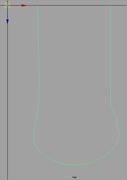
Figure 6-93: Match this profile shape with a CV curve in the top view.

4. You can adjust the curve by entering Component mode and moving the CVs to taste. Make sure the first and last CVs line up. Use the grid to help you. The final profile shape is essentially a big U with a small notch cut out of the lower-right side where the tire meets the rim. Check the size of the profile curve, and make sure it’s about the size of half the wheel in the top reference image in the top view. This profile curve will be revolved around an axis and will fill in a surface for the entire wheel. You can always scale the finished wheel later, so getting this step perfect isn’t critical.
Figure 6-94: The pivot point for the profile curve you just created is at the origin.
5. As you can see in Figure 6-94, the pivot point of the curve is at the origin, no matter where on the top grid you drew the curve. You need to move the pivot to the first CV of the curve. First, to display the CVs of the curve without entering Component mode, select the curve and choose Display ⇒ NURBS ⇒ CVs.
6. Press W to activate the Move tool, and then press Insert (Home on a Mac system or fn+Home/Left Arrow key on a Macbook Pro) to enter Pivot mode, as you did in the Solar System exercise earlier in the book. Hold down the V key to enable Snap to Points, and snap the pivot to the first CV of the curve (the upper-right corner of the curve), as shown in Figure 6-95.
Figure 6-95: Place the pivot at the beginning CV of the curve.

Creating the Revolved Surfaces
Now you can revolve the profile curve to make the base shape of the wheel as you continue by following these steps:
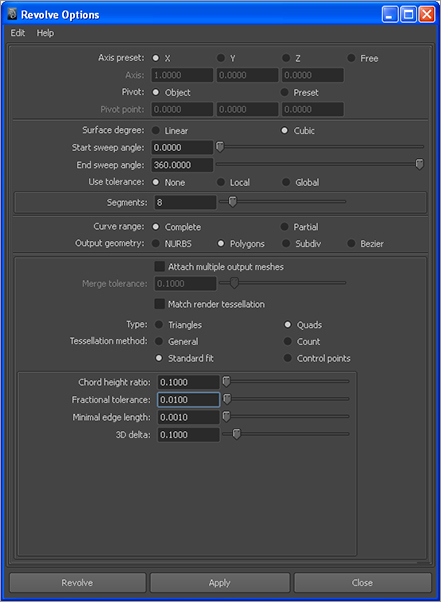
Figure 6-96: Revolve options for the wheel
1. Select the curve, and move it to the origin; now its first CV lies on the origin. Turn off CV display by selecting Display ⇒ NURBS ⇒ CVs.
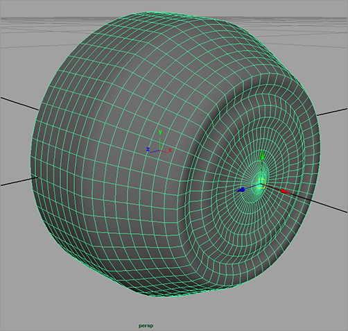
2. Enter into the Surfaces menu set, select the curve, and choose Surfaces ⇒ Revolve ❒. In the Options box, set the options as shown in Figure 6-96. Click Revolve, and your wheel appears, as shown in Figure 6-97. For more on these tessellation settings, see the “Wheel Tessellation” sidebar before you move on to the next steps and before you delete the surface history on the wheel mesh.
Figure 6-97: The wheel!

Wheel Tessellation
What are all those numbers you input for the revolve surface? Because you’re generating the wheel surface as a polygon mesh using a NURBS surfacing technique, you have to tell Maya the proper parameters for the poly surface. If the tessellation values, which are determined by the Tessellation method and the attribute values below it (as shown in Figure 6-96) aren’t just right, the wheel’s mesh will be revolved without all the details you need. These settings are deemed to be the best tessellation for the wheel through trial and error by creating the wheel, changing the tessellation values interactively, and seeing the results update through surface history.
As a test (save your scene first!), select the newly revolved wheel mesh before you delete history on it. In the Attribute Editor, you’ll see a tab for the recently created mesh called something like nurbsTessellate1. Click that tab to open its attributes, and change some of the values under the Advanced Tessellation Options ⇒ Standard Fit Options heading. Because history is still attached to this mesh, it changes the mesh interactively as you change the tessellation options. After you’ve had your fill, revert back to your saved file, and continue with the exercise at hand.
3. Move the pivot point of the wheel to the center of the rim. Name the surface wheelMesh.
4. You need to add the little nub of the wheel at the rim, as you can see in the photos back in Figure 6-92. Just as you did with the wheel’s profile curve, create a profile curve for the little inset cap. As best you can, match the shape and position to the one shown in Figure 6-98. This time, start the curve on the lower-left of the curve shown, and work your way counterclockwise up to the upper-right corner, ending the curve at the same height as the wheel at the X-axis.
5. Move the pivot point of the new profile curve to its last CV, as shown in Figure 6-99. Put the curve at the origin; its last CV should now rest at the origin.
Figure 6-98: Create a new profile curve for the hubcap detail.
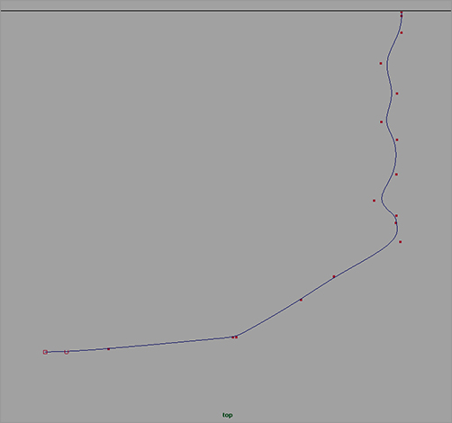
Figure 6-99: Move the pivot point.

Figure 6-100: The hubcap detail surface
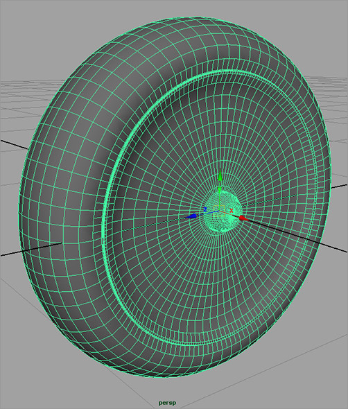
6. Select the new profile curve, and revolve a new surface using the same settings as before in Figure 6-96 (see Figure 6-100).
7. Select and move the new cap mesh into the middle of the wheel’s rim, and size the cap to fit using the side-view reference. Name the object capMesh. See Figure 6-101.
Figure 6-101: The wheel is complete!
8. If you want to adjust the shape of the wheel or the hubcap nub, you can adjust the CVs on your profile curves; the surfaces will adjust, provided history is still intact. Delete both the profile curves for the wheel and the cap, if you haven’t already. Doing so also deletes the history on the surfaces, which is fine after you’re pleased with the shape of both surfaces.
9. Select both the wheel and the cap meshes, and group them together by pressing Ctrl+G. Name the group node wheel.
10. With the wheel node selected, center the pivot by choosing Modify ⇒ Center Pivot. This places the pivot for the wheel assembly properly in the center of the wheel.
11. Using the side-view reference, position the wheel to the back of the wagon using the top wheel node to place it, as shown in Figure 6-102. If you need to, scale the wheel’s top node to fit it to the real wheel using both the side and front reference planes for sizing.
12. Duplicate the wheel, and place it on the other side of the wagon’s back end. Select the top node (wheel1), and scale it in the X-axis to -1.0 to mirror it properly.
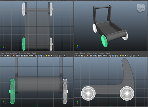
13. Duplicate both the rear wheels, and place them at the front of the wagon, as shown in Figure 6-103. Don’t worry about placing the wheels exactly where they’re shown in the front reference plane; use the side view for positioning. Due to the perspective of the photo, they won’t line up accurately in both reference planes, so it’s best to keep all the wheels lined up in the Maya scene, as you can see from Figure 6-103.
Figure 6-102: Place the first wheel.
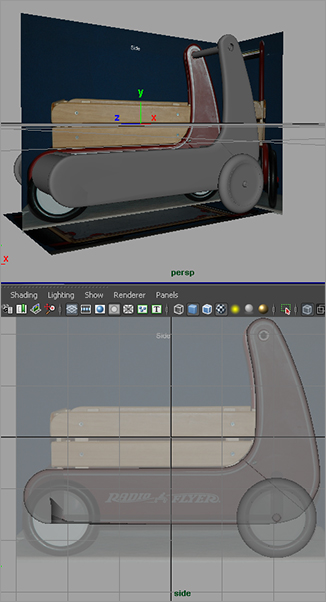
Figure 6-103: Duplicate and place the other three wheels.
14. After you’ve placed the wheels, freeze their transforms: select the four top wheel nodes, and choose Modify ⇒ Freeze Transformations. Doing so sets the transform values for the wheel nodes to 0 in translation and rotation and 1 in scale without altering them in any way.
Because the axles of the wheels aren’t very noticeable, there is no need to build them. Simply placing the wheels close to the body in the correct positions will suffice. Now you have a wagon that can roll; and, if you have a kid, you know it’ll end up rolling over your toes pretty soon. The red wagon is really starting to take shape. Enjoy a frosty beverage—perhaps a smoothie—save your work, and get ready to finish this wagon in the next sections.
You may want to load the scene file RedWagonModel_v06.ma from the Scenes folder of the RedWagon project on the CD to check your work or to skip to this point. You’ll move on to the wooden railings in the next section.