The handlebar is a pretty easy affair to create. It’s a simple cylinder that fits in the holes at the top of the side panels. However, each end has a bolt that holds the bar in place. Although you don’t have to be completely accurate and create a washer and bolt, it’s nice to add the detail of a bolt at either end of the handlebar.
Making the Handlebar
To begin the handlebar, follow along here:
1. Create a poly cylinder with Axis Divisions of 24, Height Divisions of 2, and Cap Divisions of 1.
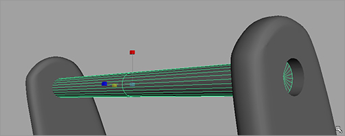
2. Scale, rotate, and position the cylinder to fit between the side panels, fitting into the holes. For the best effect, make sure the cylinder is a little smaller than the holes. Figure 6-81 shows the handlebar in place.
3. Make sure the ends of the handlebar are about halfway through the holes to make room for the bolts. Name the cylinder handlebar.
Figure 6-81: Place the cylinder.
Making the Bolts
Now, you’ll make a bolt for the handlebar in these continuing steps:
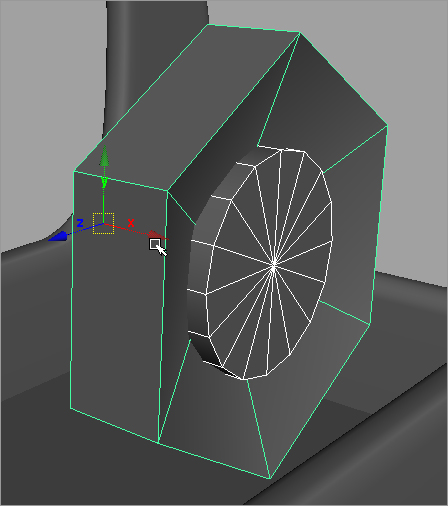
1. Create a poly cylinder with the following options: Axis Divisions = 6, Height Divisions = 1, Cap Divisions = 2, and Axis = X. (See Figure 6-82.)
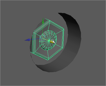
2. Select the inner faces of the cap facing forward, as shown in Figure 6-83, and move them back into the cylinder to create a depression.
Figure 6-82: Starting the bolt model
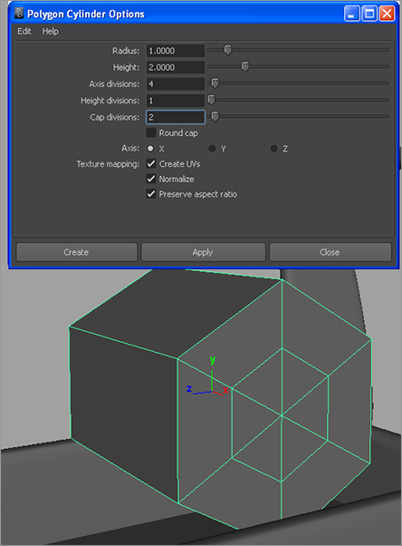
Figure 6-83: Create an indent in the cap of the bolt head.
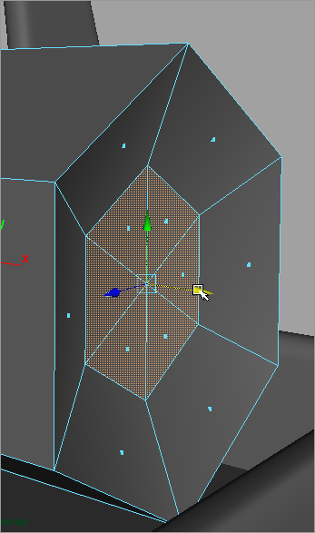
Figure 6-84: Shorten the bolt cylinder.
3. Select the back vertices of the cylinder, and move them closer to the front to shorten the cylinder, as shown in Figure 6-84. It’s still a rather large bolt, but don’t worry about that yet.
4. Create another cylinder, this time with Axis Divisions set to 16 and Cap Divisions set to 1. Scale and orient the new cylinder to fit through the bolt head slightly, as shown in Figure 6-85.
Figure 6-85: Place a cylinder slightly through the bolt head.
5. Let’s make the bolt head a lot nicer. Using the Select Edge Loop tool, select the outer loop of edges all the way around the bolt head, as shown in Figure 6-86.
Figure 6-86: Select the outer loop of edges.

6. Bevel the outer loop of edges with a Width setting of 0.3 and a Segments value of 3, as shown in Figure 6-87.
7. Select the outer loop of edges for the inner cylinder, and bevel them with the same settings. Figure 6-88 shows the result.
Figure 6-87: Bevel the end of the bolt head.

Figure 6-88: Bevel the inner cylinder.

8. Select the bolt head object, and name it boltHead. Select the inner cylinder for the bolt, and name it boltBody.
Figure 6-89: Size and position the bolt.
9. Select both the boltBody and boltHead objects and group them together (Ctrl+G). Name the new group bolt.
10. Scale the bolt group down to a good size, and place it inside the hole in the side panel up against the handlebar’s end, as shown in Figure 6-89.
Figure 6-90: Place the duplicated bolt on the other end of the handlebar.

11. With the bolt group in place and still selected, freeze its transforms by choosing Modify ⇒ Freeze Transformations.
12. To make another bolt for the other side of the handlebar, simply duplicate the bolt group by pressing Ctrl+D. Then, with the duplicate group (bolt1) selected, enter a scale of -1.0 in the ScaleX value in the Channel Box. (See Figure 6-90.)
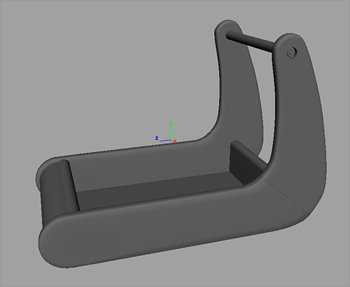
Figure 6-91 shows the progress of the wagon so far. With the body of the wagon pretty much finished, you can move on to the wheels.
Figure 6-91: The wagon so far…