
Figure 6-71: Move the top reference plane down a bit.

Now that you’ve finished the hardest part of the process, you can concentrate on getting the body of the wagon built between the two side panels (called out as C in Figure 6-17 earlier in the chapter).
Look in the top view, and you probably won’t see all the side panels. This is because the top reference plane is blocking it. Select the top reference plane, and move it down as shown in Figure 6-71 to give you a little more room in which to work.
Creating the Floor
To begin the floor of the wagon, follow these steps:
1. In the top view, create a polygonal cube. Scale and position it to fit the bottom of the wagon body using all the views as reference, as shown in Figure 6-72.
2. Using the Insert Edge Loop tool, insert edge loops at the ends of the wagon’s floor at about the same thickness as the side panels, as shown in Figure 6-73.
3. Select both the new faces created on top of the floor. Choose Edit Mesh ⇒ Extrude to pull up the ends to just under the lip of the panels to make a box, as shown in Figure 6-74.
Figure 6-72: Place and scale the box to be the bottom of the wagon body.

Figure 6-73: Insert Edge Loop divisions at both ends of the floor.
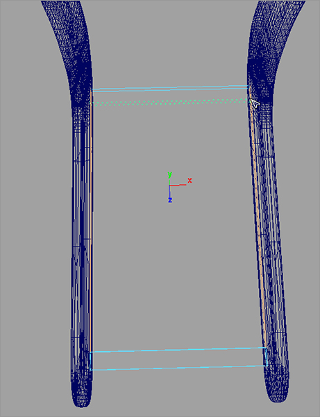
Figure 6-74: Extrude the top faces to make an open-faced box.

4. You need to round the new edges of the box to match the panels. Select the edges of the front and back box ends, as shown in Figure 6-75.
5. Choose Edit Mesh ⇒ Bevel ❒. Set Width to 1.0 and Segments to 12. Click Bevel, and your edges are e rounded beautifully, as shown in Figure 6-76. Name the cube wagonFloor.
Figure 6-75: Select these edges.
Figure 6-76: Bevel does a great job of rounding these edges.

Creating the Bullnose
Next, let’s create the bullnose in front of the wagon body (part D, called out earlier in Figure 6-17), as shown in Figure 6-77.
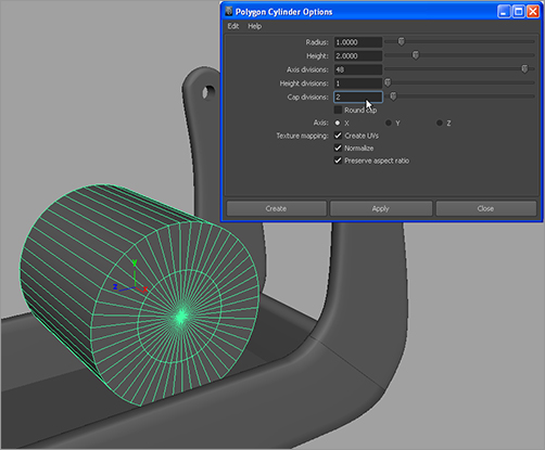
1. Create a polygonal cylinder with the options shown in Figure 6-78. Set Radius to 1, Height to 2, Axis Divisions to 48, Height Divisions set to 1, Cap Divisions to 2, and Axis to X.
Figure 6-77: The bullnose
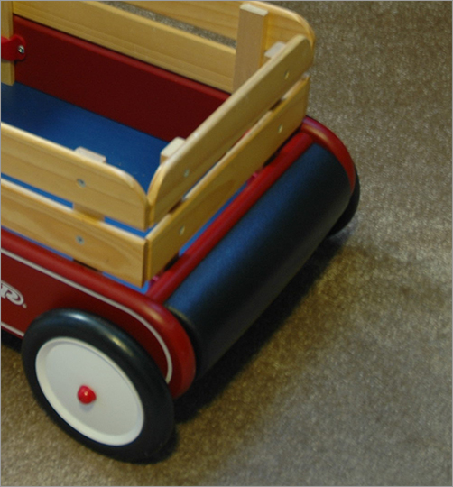
Figure 6-78: Create a poly cylinder with these settings.
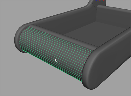
2. You only need the front half of the cylinder. In the top view, select the cylinder, and choose Edit Mesh ⇒ Cut Faces Tool ❒. In the Options box, set Cut Direction to XY plane, and select the Delete Cut Faces check box. Click Cut, and half of the cylinder immediately deletes at the center line, as shown in Figure 6-79. You could use the special manipulator to move the cut plane back and forth to cut the cylinder at a different place; but because it’s already at the center, you’re fine.
3. Press W to enter the Move tool and exit the Cut Faces tool. Move and scale the cylinder to fit into the front of the wagon, as shown in Figure 6-80. Name the cylinder bullnose. The bullnose is ready!
4. Select both the wagonFloor and bullnose objects, and delete their histories.
Figure 6-79: Cut the cylinder in half.
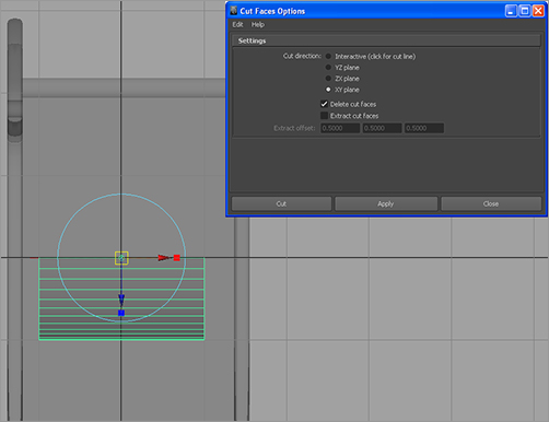
Figure 6-80: The bullnose is in place.
Save your work to a higher version number. You may want to load the scene file RedWagonModel_v05.ma from the Scenes folder of the RedWagon project on the CD to check your work or to skip to this point.
The wagon’s body is finished. You can insert the handlebar into the side panels.