
Now that your reference is all set, let’s get to work building the model. Here is where the sweat comes in. There are many ways to model the same object, but they all basically stem from the same procedures you’ve seen in the previous chapters.
Shaping the A Panel
You’ll start with the first side piece, marked A in Figure 6-17. Follow these steps:
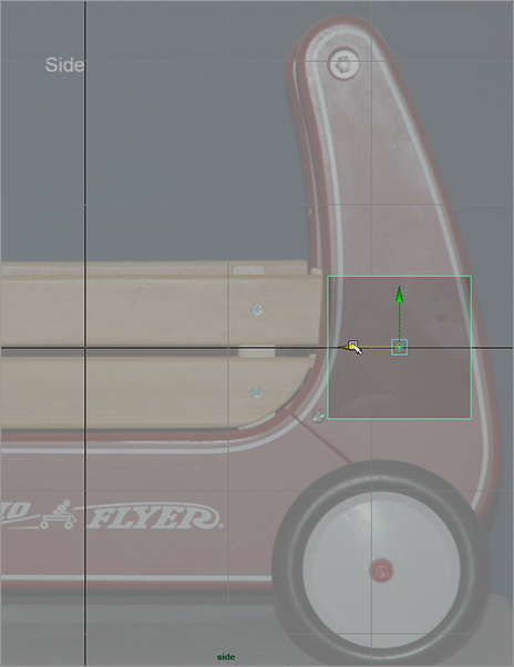
1. Enter the Polygons menu set. Create a default poly cube, and place it in the side view in front of the A piece, as shown in Figure 6-18.
Figure 6-17: You’ll build the wagon in this order.
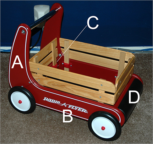
Figure 6-18: Place a poly box for the first side.
Menu Set Hot Keys
You can use the following hot keys to toggle between menu sets:
| F2 | Animation |
| F3 | Polygons |
| F4 | Surfaces |
| F5 | Dynamics |
| F6 | Rendering |
2. RMB+click the cube, and select Vertex from the marking menu to enter Vertex Selection mode. Carefully move the corners to place them as shown in Figure 6-19. To place the vertices, use only the Z- and Y-axis handles for the Move tool so that you don’t accidentally move the vertices in X as well.
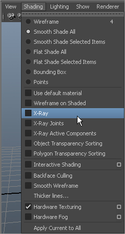
3. To be able to see the texture view of the reference planes through the shaded gray cube you just created, you need to enter X-Ray mode. In any of the view panels, click Shading ⇒ X-Ray, as shown in Figure 6-20.
Figure 6-19: Place the four corners of the box to fit the A piece.
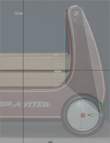
Figure 6-20: In the view panels, turn on X-Ray Shading mode. (The side view is shown here.)
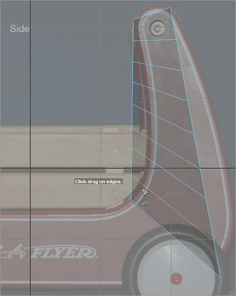
4. This shape obviously won’t fit the A panel. You need to add edges to define this mesh better. Choose Edit Mesh ⇒ Insert Edge Loop Tool. With the Triangular Tool icon, click along the vertical edges to place seven new edge loops, as shown in Figure 6-21. RMB+click the cube, select Vertex to enter Vertex Selection, and move the new vertices to fit the shape of the A panel, also shown in Figure 6-21.
Figure 6-21: Insert edge loops to create more edges and vertices, and then shape the cube to match the A panel as shown here.
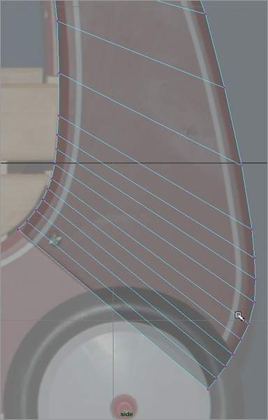
5. The area around the bend just above the back wheel needs more edge loops to fit the curvature better. Using the Insert Edge Loop tool, insert seven more edge loops as shown in Figure 6-22. In Vertex mode, move the vertices to fit the curvature as shown in Figure 6-23.
Figure 6-22: Insert more edge loops.

Figure 6-23: Move the new vertices to match the curvature.
6. Turn your attention to the top curvature. Using the Insert Edge Loop tool, add four new edge loop divisions to the top of the A panel (see Figure 6-24). Move the vertices to match the curvature, as shown in Figure 6-25.
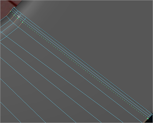
7. You need to match the very top curvature by adding vertical edge loops to the mesh. Using the Insert Edge Loop tool, click and drag to add five new vertical edge loop divisions, as shown in Figure 6-26.
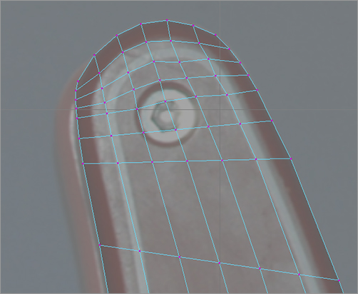
8. Move the vertices to match the top curvature, as shown in Figure 6-27. Try to place the vertices evenly.
Figure 6-24: Add new edge loop divisions to the top curvature.

Figure 6-25: Move the new vertices to match the top curvature.
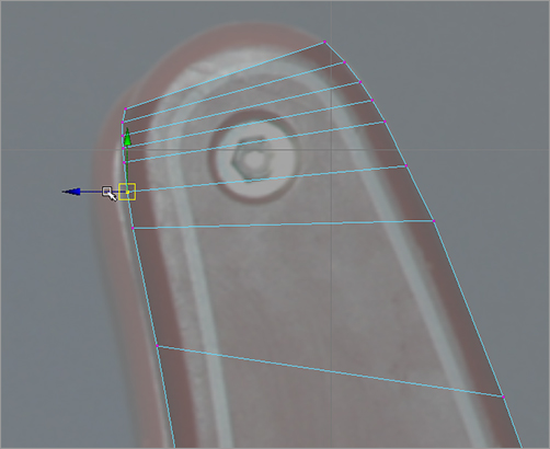
Figure 6-26: Insert five new vertical edge loop divisions.

Figure 6-27: Match the curvature of the top.
9. The mesh for the A panel should look like Figure 6-28. It’s too wide and not in place. Using the front view, position the mesh to fit where the A panel goes. Scale the width down to match the width of the panel. See Figure 6-29.
Figure 6-28: The current state of the mesh
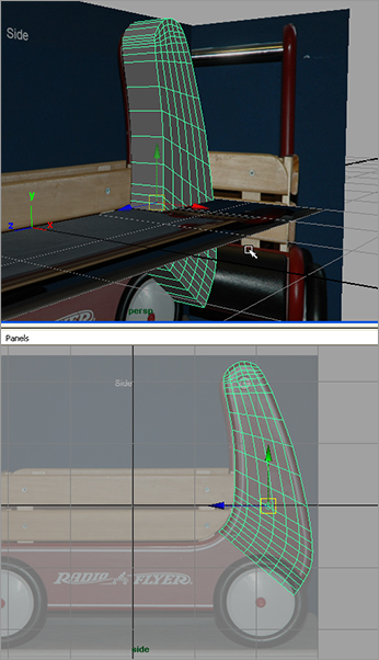
Figure 6-29: Scale and position the mesh in the front view to match the actual A panel.

Fixing Problem Areas
You may notice an awkward polygon face at the top corners of the mesh, as shown in Figure 6-30. This polygon will break apart when you try to round the edges as you can see with the real wagon (Figure 6-17).
Let’s add a couple of edges to these faces to circumvent any problems that may arise when you bevel the edges to round them to match the real wagon:
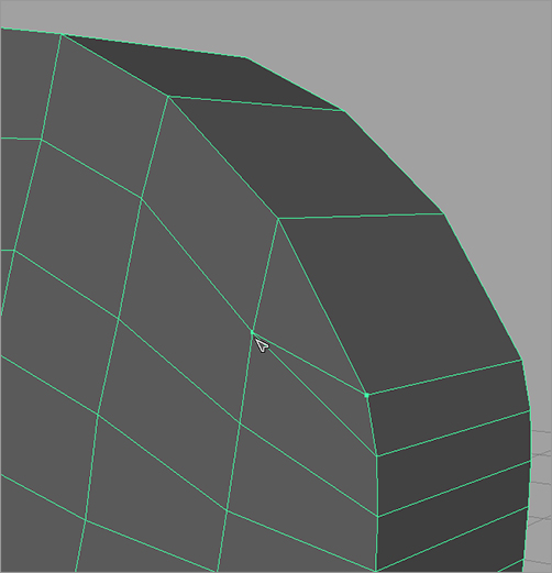
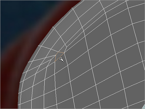
1. Choose Edit Mesh ⇒ Split Polygon Tool, and click and drag to place the first end of the edge at the corner shown in Figure 6-31. Place the other end of the new edge as shown in Figure 6-32.
2. Use the Split Polygon tool to place a new edge for the awkward polygon on the reverse side of the A panel, as shown in Figure 6-33.
Figure 6-30: An awkward polygon corner may cause problems when you round the edges.

Figure 6-31: Begin the new edge here.
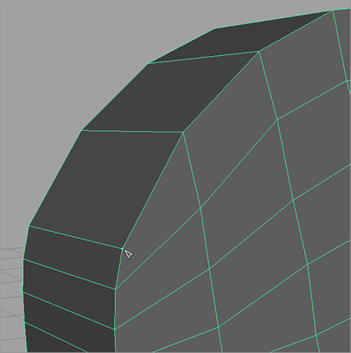
Figure 6-32: The new edge

Figure 6-33: Add an edge to the reverse side’s awkward polygon face.
3. Use the Split Polygon tool to place new edges for the awkward polygons on the front and back sides for the right side of the A panel, as shown in Figure 6-34.
4. As you can see in Figure 6-17, the panels on the real wagon are rounded at the edges. You can use Bevel to round the three topside edges of the panel, leaving the bottom rim of the panel flat for now. In the Polygons menu set, choose Select ⇒ Select Edge Loop Tool. Double-click one of the edges to select the entire edge loop for the front of the panel. Double-click one of the edges to select the loop of edges on the back side of the panel, as shown in Figure 6-35. Notice that the bottom loop of edges isn’t selected; this is fortunate for you in this case. You can always select each of those edges individually; however, the Select Edge Loop tool makes it quite a bit easier.
Figure 6-34: Add edges to the awkward polygons on the right side (front and back shown; top and bottom, respectively).

Figure 6-35: Select the edge loops for the front and back.
5. With those edge loops selected, choose Edit Mesh ⇒ Bevel ❒ to open the Options box for the Bevel command. Set Width to 1.0 and Segments to 2, as shown in Figure 6-36. Click Bevel to create the beveled edge shown in Figure 6-37. It’s not quite as round as it should be, but you’ll tackle that with a Smooth operation in the following steps.
Figure 6-36: Settings for the Bevel operation

Figure 6-37: The rounded edges after the Bevel

Smoothing the Panel
Next, you’ll smooth the panel for a better fit to the real panel and a nicer look overall. Because the panel isn’t as rounded as you’d like, you’ll want to add a Smooth to the mesh, as you did in Chapter 4, “Beginning Polygonal Modeling” with the hand model. With the panel mesh selected, press 3 to display the panel as it will look after it’s smoothed. Notice that the panel looks subtly but appreciably better with the Smooth preview. However, the bottom of the panel becomes too smooth, as you can see in Figure 6-38. To fix this, you’ll add divisions to the bottom in the next step:
1. Press 1 to return to the normal view of the mesh.
2. Use the Insert Edge Loop tool to insert three new edge loops at the bottom of the panel, as shown in Figure 6-39. Toggle between previews 1 and 3 to see how much better the smoothing will look at the bottom.
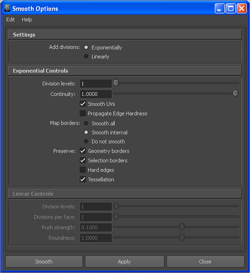
3. Now for the Smooth operation. Select the panel, and make sure you’re back in normal mesh view by pressing 1. Choose Mesh ⇒ Smooth ❒. In the Options box, make sure Exponentially is selected and Division Levels is set to 1 (the default settings), as shown in Figure 6-40. Click Smooth. The A panel should look much nicer. Check it against the reference planes, and it should fit better.
Figure 6-38: In the preview, the bottom of the A panel becomes too smooth when you press 3.
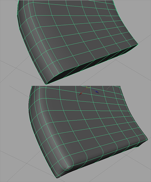
Figure 6-39: Insert three new edge loops at the bottom of the panel.

Figure 6-40: The Smooth options
4. Look in the Channel Box to see the history of all the work you did on the project (see Figure 6-41). Let’s work cleanly and get rid of this history. With the mesh still selected, choose Edit ⇒ Delete by Type ⇒ History.
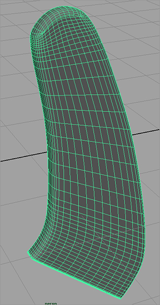
5. Select the mesh, and name it Apanel in the Attribute Editor or Channel Box. Your finished panel shape is shown in Figure 6-42. While you’re at it, name the reference planes as well: sideRef, topRef, and frontRef.
Save your work, and version it up so you don’t write over your previous scene files. You can load the scene file RedWagonModel_v02.ma from the Scenes folder of the RedWagon project on the CD to check your work or to skip to this point.
To keep track of your progress, you can save the file of your wagon scene manually and rename it with new version numbers, or you can use Incremental Save to let Maya make backups for you. (Make sure the option is turned on through File ⇒ Save Scene ❒.)
Figure 6-41: So much history!

Figure 6-42: The finished panel shape
Using Booleans
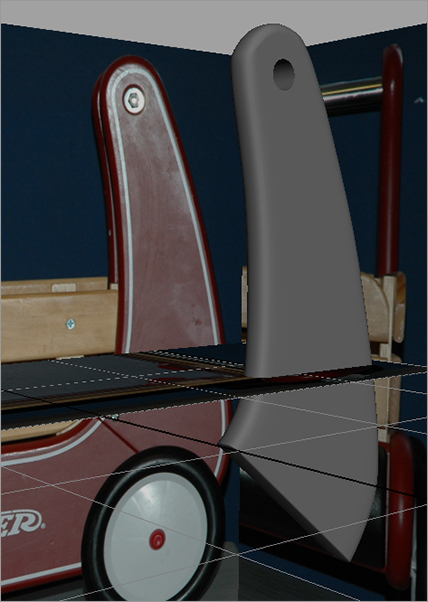
Now that you’ve worked out the shape of the A panel and the model is clean and named, you’ll use a Boolean operation to cut a hole in the top of the panel for the handlebar that crosses between the panels (see Figure 6-43).
Figure 6-43: The handlebar
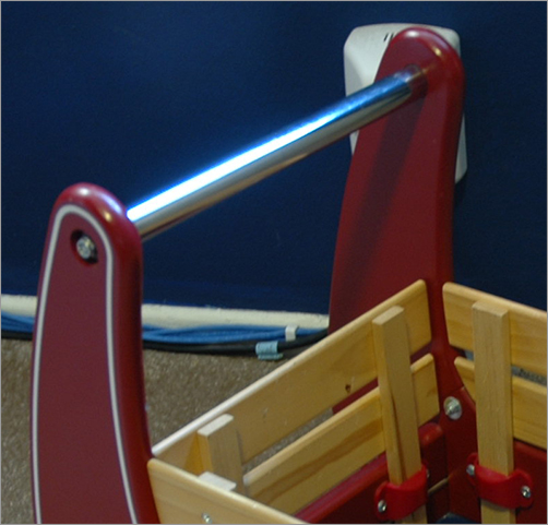
Booleans are very impressive operations that allow you to, among other things, cut holes in a mesh fairly easily. Basically, a Boolean is a geometric operation that creates a shape from the addition of two shapes together (Union), the subtraction of one shape from another (Difference), or the common intersection of two shapes (Intersection).
Be forewarned, however, that Boolean operations can be problematic. Sometimes you get a result that is wrong—or, even worse, the entire mesh disappears and you have to undo. Use Booleans sparingly and only on a mesh that is clean and prepared. You’ve cleaned and prepped your panel mesh, so there should be no problems. (Actually, there will be a problem; but that is half the fun of learning, so let’s get on with it.)
Creating the Boolean Object
For the red wagon, you need to cut a hole into the panel to bolt in the handlebar, as you can see in Figure 6-43. In this case, you’ll use a Difference Boolean. You need to cut a cylindrical hole out of the mesh at the location of the handlebar (refer to the side reference plane in the Side view panel). For a Boolean, you need two meshes. The panel is the first mesh to be affected, and the second mesh will be a polygonal cylinder to represent the handlebar.
Make sure Interactive Creation is turned off, and follow these steps:
1. In your scene, create a polygonal cylinder with Axis Divisions of 24 and Height Divisions of 2 (choose Create ⇒ Polygon Primitives ⇒ Cylinder r), as shown in the Polygon Cylinder Options box in Figure 6-44.
Figure 6-44: The Polygon Cylinder creation Options box

2. Using the side view as reference, scale, orient, and place the cylinder to match up with the handlebar. Scale the cylinder to go all the way through the panel mesh, as shown in Figure 6-45. Try to center the cylinder’s middle at the center line of the width of the mesh.
3. First select the panel mesh, and then select the handlebar cylinder. Choose Mesh ⇒ Booleans ⇒ Difference. The cylinder disappears, and the panel mesh now has a hole cut through it, as shown in Figure 6-46.
Figure 6-45: Place the handlebar cylinder.

Figure 6-46: The Boolean cuts a hole in the mesh.
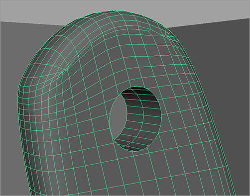
4. But now you have a problem! It’s not easily seen, but there is a tear in the mesh, close to the rounded edge. Figure 6-47 shows the location of the tear, and Figure 6-48 shows a closer rendered view of the tear. It goes all the way through. If you don’t see a tear in your mesh, you can skip the next section, “Fixing Tears,” if you wish.
Figure 6-47: There is a tear between the faces.
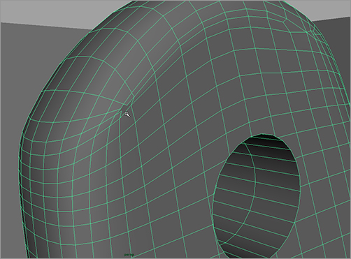
Figure 6-48: A render of the mesh shows the tear on both sides of the mesh panel.
Fixing Tears
Remember when I said Booleans can be problematic? Here is a perfect example. You’ll work on fixing the tear by first moving and merging vertices. Let’s begin on the front side of the mesh. You’ll have to repeat these steps for the tear on the back side of the mesh:
1. Select the entire mesh object, and delete its history (Edit ⇒ Delete by Type ⇒ History).
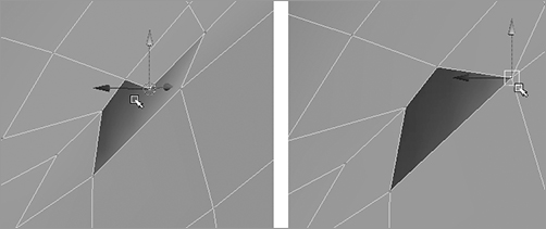
2. Select the vertex shown on the left in Figure 6-49, and snap it (with Point Snap) to the vertex just above it, shown on the right.
3. Select both those vertices to merge them. Choose Edit Mesh ⇒ Merge. The vertices don’t become one, as you saw in an earlier exercise in Chapter 4.
4. Select the vertex shown on the left in Figure 6-50, and snap it onto the vertex just below it, as shown on the right.
Figure 6-49: Select and snap the vertex to begin cleaning the tear.

Figure 6-50: Select and snap the second vertex to clean the tear.
5. Select both vertices, and merge them as in step 3. Now you have a clean hole in the front of your panel’s mesh that can be filled with a simple four-sided polygon face.
6. Use the same procedures in steps 2 through 5 to clean the tear in the back of the panel’s mesh, as shown in Figure 6-51.
7. You now should have two simple four-sided holes in your mesh, front and back. Select the entire mesh, and choose Mesh ⇒ Fill Hole. Bam! Maya fills in both tears in the front and back of the panel mesh with a simple four-sided polygonal face. Figure 6-52 shows the newly formed face on the front side of the mesh.
Figure 6-51: To clean up the tear, snap the vertices on the back side of the panel’s mesh.

Figure 6-52: The tears are filled in with new faces.
8. There is a little scar from the tear that you can probably see in the Shaded mode of the mesh (see Figure 6-53). This scar won’t show up in your renders after you texture and shade the wagon in the next chapter. Otherwise, your fix works great. Select the mesh, and delete its history. Rename the mesh back to Aplane, because the Boolean operation changed the mesh’s name to polySurface1.
Figure 6-53: The fix works great. It leaves a little scar that won’t show in your renders later in the book.
Cleaning the Faces Around the Handlebar Hole
With the tears fixed, turn your attention to the faces that surround the hole you cut for the handlebar. Although there are no longer any glaring issues evident, several faces that border the hole have more than four sides. This isn’t always an immediate problem, but rendering and modeling issues may crop up further down the road of you don’t clean up these faces:
1. Select the faces that surround the handlebar hole one by one for the front side of the mesh. Then, with the Shift key depressed, select the faces around the hole on the back side of the mesh. Don’t select the faces that make up the inside tunnel of the hole. See Figure 6-54.
2. With the faces selected, choose Edit Mesh ⇒ Add Divisions ❒, and set the options as shown in Figure 6-55.
Figure 6-54: Select the faces that border the hole.

Figure 6-55: The Add Divisions settings
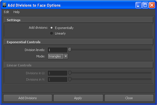
Figure 6-56: Add Divisions cleans up the faces by aligning the segments with new edges and faces.
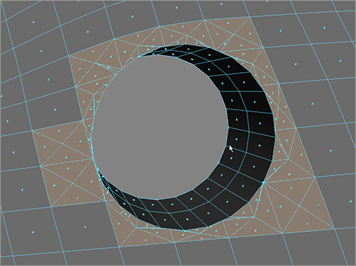
Figure 6-57: Final A panel in perspective view
3. The faces around the hole fill in with new divisions that match the way the hole is segmented and cut. See Figure 6-56.
4. Select the mesh, and delete its history.
Figure 6-57 shows the final A panel in perspective view. Save your work! You can load the scene file RedWagonModel_v03.ma from the Scenes folder of the RedWagon project on the CD to check your work or to skip to this point.
Shaping the B Panel
Now that everything is nice and clean and your A panel mesh is finished, you’re ready to move on to the B panel (shown earlier in Figure 6-17):
1. Create a new polygon cube, and place it in the side view to line up with the B panel. Move the corner vertices in the side view to roughly line up, as shown in Figure 6-58.
Figure 6-58: Set up the new polygonal cube to fit roughly over the B panel.

2. You need to add edge loops as you did with the A panel to match the curvatures of the B panel in the real wagon. Add six edge loops as shown in Figure 6-59 for the right side of the panel.
3. Move the vertices to match the curvature of the B panel, as shown in Figure 6-60.
Figure 6-59: Add edge loop divisions.
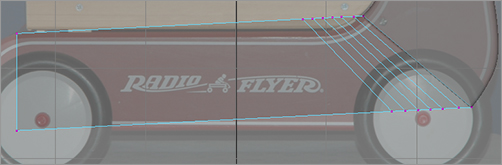
Figure 6-60: Move the new vertices to match the curvature of the B panel.

4. Select the B panel mesh, and scale and position it in the front view to line up with the B panel of the real wagon in the front reference plane, as shown in Figure 6-61.
Figure 6-61: Line up the position and size of the panel.

5. To make the curvature of the B panel at the front of the wagon, use the Wedge procedure you used in the hand exercise in Chapter 4. First, look at the end face of the B panel. You need to split that into two faces for a proper Wedge.
6. Select Edit Mesh ⇒ Split Polygon Tool. Click and drag a point on one edge of that end face to put it at exactly 50 percent, as shown to the left in Figure 6-62. Release the mouse button to place the point, and then click and drag the opposite edge to place the other point for the new edge also at 50 percent as shown on the right in Figure 6-62. Notice that the readout in the very bottom-left corner of the UI shows the percentage as you drag the point on either edge, also shown in the bottom-left corner of both sides in Figure 6-62.
Figure 6-62: Split the end face in half to prep for the Wedge.

Figure 6-63: Select the top face as well as its bottom edge.
7. Right-click the mesh, and choose Face from the marking menu to enter Face Selection. Select the top face of the newly split end. Then, RMB+click the mesh, and select Edge to enter Edge Selection mode. With the Shift key depressed, Shift+select that new middle edge, as shown in Figure 6-63.
8. Choose Edit Mesh ⇒ Wedge Face ❒. Set Arc Angle to 180 and Divisions to 10. Click Wedge Face, and the end of the B panel is rounded at the end. See Figure 6-64.
9. In the side view, select all the vertices at the end and position the arc to match the curvature of the wagon’s real B panel. See Figure 6-65.
Figure 6-64: Wedge the face at the end to create the curvature of the panel.
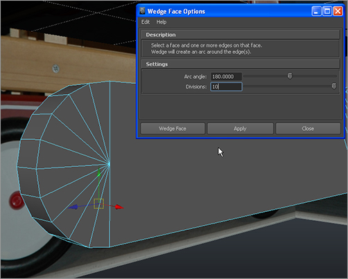
Figure 6-65: Move the vertices as a whole to fit the end curvature to the real curve of the wagon’s panel.

Rounding the Edges
Now, you’ll round the edges of the B panel in these continuing steps:
1. Using the Select Edge Loop tool (Select ⇒ Select Edge Loop Tool), select the edges that run along the B panel mesh. Don’t select the edges where the B panel meets the A panel. See Figure 6-66.
Figure 6-66: Select these edge loops that run along both edges of the panel.
2. Choose Edit Mesh ⇒ Bevel ❒, and set Width to 0.5 and Segments to 2 as shown. Click Bevel, and your B panel edges will be rounded as shown in Figure 6-67.
3. With the mesh selected, toggle in and out of smooth mesh preview using the 1 and 3 keys to see how the mesh would look after being smoothed. You’ll have issues with the end that meets the A panel, so you’ll have to insert edge loop divisions at that end to prevent the model from becoming too smooth. Using the Insert Edge Loop tool, insert three new edge loops at the very end of the B panel where it meets the A panel, as shown in Figure 6-68.
Figure 6-67: Bevel to round the edges of the B panel.

Figure 6-68: Insert edge loops to prevent this end from smoothing too much.
4. Select the B panel mesh, and choose Mesh ⇒ Smooth ❒. Set Add Divisions to Exponentially and Division Levels to 1. Click Smooth, and your B panel is done! See Figure 6-69.
5. Select the mesh, name it Bpanel, and delete its history.
Figure 6-69: Smooth the B panel mesh.

Cleaning Up the Scene
Now, let’s put these objects into a good hierarchy and clean everything up. Select both the A and B panels, and freeze their transforms: choose Modify ⇒ Freeze Transformations. This resets the values for the mesh’s position and the rotation to 0 in all axes and sets the scale values back to 1. It doesn’t adjust the objects in the slightest; it only resets their values back to an original value to keep things nice and clean. After you froze the transformations, the meshes stayed in place, but their values in the Channel Box reverted back to 0s (Translate and Rotate) and 1 (Scale).
Freeze Transformations (also referred to as freezing transforms) sets the values of the object’s settings back to their defaults (that is, it sets Translate and Rotate back to 0 and Scale back to 1). It doesn’t reset the size or positions—just the number values in the attributes. This is useful for getting an object back to default conditions without losing all the work done to it. Using Freeze Transformations keeps things clean as you work, and doing so is usually a good idea when you’re working with patches.
With both the panels still selected, group them together by choosing Edit ⇒ Group or by pressing Ctrl+G. Name the new group rightSidePanels.
Figure 6-70: Duplicate and position the panels to the other side of the wagon.

With the rightSidePanels top node selected, duplicate the panels by pressing Ctrl+D or by choosing Edit ⇒ Duplicate. Move them in the front view to line up with the left side of the wagon, as shown in Figure 6-70. Name the duplicated group leftSidePanels. Notice that the panels don’t line up perfectly to the reference images. This is due to the perspective in the photos and is to be expected. Use the upper part of the panels to line everything up, as shown in Figure 6-70.
Save your work to another version number. You may want to load the scene file RedWagonModel_v04.ma from the Scenes folder of the RedWagon project on the CD to check your work or to skip to this point.