
Rigging the Locomotive, Part 1
In this section, you’ll return to the locomotive you modeled in Chapter 4, “Beginning Polygonal Modeling,” and put your new animation skills to use.
Load the file locomotive_model_v4.mb, which is the completed model of the locomotive from the Polygon Modeling exercise in Chapter 4. You can find it in the Scenes folder of the Locomotive project on the CD.
The Scene Setup
Figure 8-41: The locomotive’s Outliner view

It’s important to keep animation in mind as you build a model. In particular, making a good scene hierarchy is crucial to getting a smooth animation workflow going. That’s why, when you built the locomotive in Chapter 4, you used the Outliner to make sure the objects in your scene were grouped logically. Now you’re going back in to make sure you have good organization before beginning the task of rigging this thing for animation.
Figure 8-41 shows the organization of the locomotive as it stands from Chapter 4. Later, you’ll use a more finely detailed and prettier locomotive model to rig that is already grouped properly, using the intentions outlined here. This scene is in fairly good shape, but you have to identify the parts of the locomotive that you need to rig, determine how they will move, and decide what is the best hierarchy for the model from there.
The major moving parts of the engine are the wheels and the steam pump drive mechanism. The wheels, of course, need to rotate, as wheels do, and the steam pump drives the wheel arms back and forth, which is what drives the main wheels to rotate. Aside from animating some steam pumping out of parts of the engine, which we’ll cover in Chapter 12, “Maya Dynamics and Effects,” this is the basic rigging for the locomotive. First, you need to make sure the hierarchies are settled well and the pivot points are in their proper places.
The locomotive_model_v4.mb scene file has a well-organized hierarchy, but it needs some help to make rigging easier. Be sure all the individual wheel arms have their pivots at the base, as shown in Figure 8-42. Use Insert (or the Home key on a Mac—MacBook users also need to press the fn [function] key to access the Home function using the arrow key) to move the pivots as needed. You’ll rig these wheel arms using IK bones in the next chapter.
Figure 8-42: Check the pivot points.

Figure 8-43: Check the hierarchy and pivot placement for the wheel.
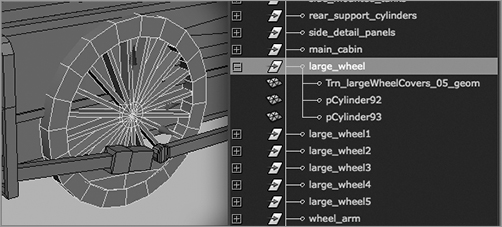
Be sure all the elements that make up a wheel are grouped and that the group’s pivot point is centered for all the wheel groups, as shown in Figure 8-43.
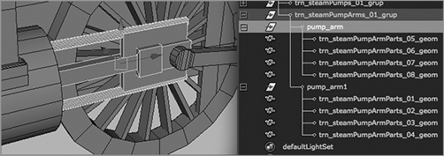
Finally, for this simple rig, make sure the steam pump arm elements are properly grouped and that the pivot is placed as shown in Figure 8-44.
If your locomotive is in organizational disarray, identify all the moving parts first, and then begin grouping them logically. Place pivots appropriately, and you’re all set. The scene file locomotive_anim_v1.mb in the Locomotive project on the CD has the locomotive scene file with the pivots and grouping already finished, as discussed earlier.
Figure 8-44: Place the pivot for the pump arm.
If the pivots and groupings are off, you’ll notice as soon as you begin to animate; things just won’t rotate on the correct axis, and pieces won’t follow properly. The wheels, for example, may wobble around their axle.
For more practice in grouping and hierarchies, you can load locomotive_anim_v1.mb from the CD, ungroup everything in the scene, and piece it all back together. To ungroup everything, select the top node of the locomotive, and choose Edit ⇒ Ungroup. Doing so ungroups the major parts of the locomotive. With those groups selected, ungroup again to flush out individual geometry. You can also load locomotive_anim_v1_B.mb from the CD; it has all the major groupings removed. Then, regroup and repivot everything. This will be great practice and boatloads of fun!
Selection Handles
Figure 8-45: Selection handles make selecting a group of objects much easier.

Using selection handles makes selection easier and work flow faster, so turn on selection handles for each of the groups you’re animating. Select the wheel groups in the Outliner, and then choose Display ⇒ Transform Display ⇒ Selection Handles. Select the wheel arm groups, and turn on their selection handles as well. Figure 8-45 shows the selection handles enabled for the wheel, pump arm, and wheel arm.
How selection handles work depends on Maya’s selection order. Selection order, which you can customize, sets the priority of one type of object over another when you try to select in a work window. After the selection handles for the locomotive’s wheels and drive arms are turned on, only the handles will be selected (and not the whole locomotive) when you make a marquee selection that covers the entire locomotive. Handles have a high selection priority by default, so they’re selected above anything else.
Animating the Locomotive
Animating most of the locomotive is straightforward. Simple rotations will make the wheels turn. Translating the locomotive’s top node will move the entire object. This, however, leaves out the drive mechanism with the steam pump and the wheel and pump arms. You’ll rig these to animate automatically in the next chapter, using IK handles and connections.