
Panels and Frequently Used Windows
The main focus of Maya is, of course, its work windows (called panels)—the perspective and orthographic views. You use these windows to create, manipulate, and view 3D objects, particles, and animations. By using the mouse, you can navigate in these views easily. Navigation in almost all panel views involves a combination of mouse control and keyboard input.
Perspective/Orthographic Windows
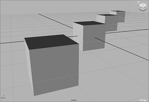
The default Maya layout begins with a full-screen perspective view, as shown in Figure 3-10. This is essentially a camera view and expresses real-world depth through the simulation of perspective. In this window, you can see your creation in three dimensions and move around it in real time to get a sense of proportion and depth.
Figure 3-10: The full perspective view
Shortcuts to Viewing
Here’s a summary of the most important keyboard shortcuts. Keep in mind that the Option key is used on a Macintosh in place of the Alt key on a PC. See Chapter 2 for more details.
Alt+MMB+click Tracks around a window.
Alt+RMB+click Dollies into or out of a view.
Scroll Wheel Dollies into or out of a view.
Alt +LMB+click Rotates or orbits the camera around in a Perspective window.
Alt+Ctrl+click and Drag Dollies your view into the screen area specified in your mouse drag.
ViewCube Allows you to change views in a panel easily.
Macintosh Keys The Option key on a Mac is used as the Alt key on a PC.
By pressing the spacebar, you can switch your view from the full-screen perspective to the four-panel layout shown in Figure 3-11. Pressing the spacebar again returns your active view panel to Full-Screen mode.
Figure 3-11: The four-panel layout
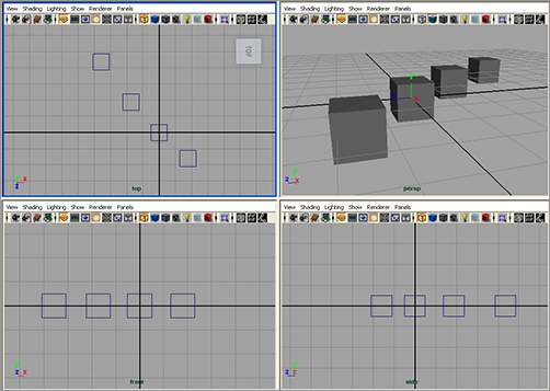
Orthographic views (top, front, and side) are most commonly used for modeling, because they’re best at conveying exact dimensions and size relationships. Even though the cubes in the Perspective window are all the same size, the perspective view, by definition, displays the cubes farther away as being smaller than those closer to you. Orthographic views, however, display exact proportions so that you can see the four cubes as being identical in size and shape.
The four-panel layout gives you accurate feedback on the sizing and proportionality of your models. In general, you’ll probably prefer to start your modeling in orthographic view and use the perspective view(s) for fine-tuning and finishing work and for setting up camera angles for rendering. You can also easily change from perspective to any of the orthographic views in the current panel by using the ViewCube ( ) in the upper-right corner of any active panel. For more information about this topic, see Chapter 2.
You can easily adjust the panel layouts of your screen by using any of the six presets in the Tool Box on the left side of the screen or by choosing Window ⇒ Saved Layouts. Furthermore, you can replace each view panel by choosing another panel name from the list in the Panels menu in the bar at the top of each view. From this menu, you can choose any modeling view, orthographic or perspective, or another window to best suit your workflow. You can also change the size of these windows by clicking and dragging the separating borders between the panels.
By default, each panel displays a grid that you can adjust by choosing Display ⇒ Grid ❒. The grid is made of actual units of measure that you can adjust. Choose Window ⇒ Settings/Preferences ⇒ Preferences to open the Preferences dialog box; and, in the Settings section, make your adjustments.
Levels of Detail
Try This In the four-panel layout (click the second Layout icon in the Tool Box), create a NURBS sphere by choosing Create ⇒ NURBS Primitives ⇒ Sphere. Your cursor turns into a small black cross, and “Drag on the grid” appears in the middle of your panels.
Creating a primitive by clicking and dragging to specify its size and position only works when Interactive Creation is turned on. You’ll find this option when you choose Create ⇒ NURBS Primitives or Create ⇒ Polygon Primitives. When this option, at the top of each of those menus, is selected, you can click and drag the primitive you’re creating. When it’s unselected, the primitive appears at the origin in 3D space.
Click and drag the cursor to create a sphere of any size, as shown in Figure 3-12. You’ll notice its primary attributes in the Channel Box.
Press 2, and you’ll see the wireframe mesh get denser. Press 3, and the mesh will get even more dense. You can view all NURBS objects, such as this sphere, in three levels of display. Pressing 1, 2, or 3 toggles between detail levels for any selected NURBS object.
NURBS is a type of surface in Maya that lets you adjust its detail level at any time to become more or less defined as needed. The display detail keys (1, 2, 3) adjust the level of NURBS detail shown in the panels only.
Figure 3-12: NURBS display smoothness

When you have a polygonal object selected, you may also press 1, 2, or 3 for levels of detail on the smoothness of the polygonal mesh. In this case, the level of detail is a preview of what the polygon object will look like after you apply a smoothing function on it. It isn’t a display of the level of detail of the current object, but again just a preview of what it would look like when you smooth it. Polygonal modeling and smoothing objects are covered in Chapter 4.
Wireframe and Shaded Modes
When you’re working in the windows, you can view your 3D objects as either wireframe models (as in Figure 3-12) or as solid, hardware-rendered models called Shaded mode (see Figure 3-13). Wireframe mode is the fastest because it makes fewer processing demands on your computer. However, Shaded mode can be pretty quick too, depending on your graphics card and your system processor.
Within Shaded mode, you can select varying degrees of shading detail. You can cycle through the levels of detail by pressing 4, 5, 6, and 7. Wireframe mode is 4, Shaded mode is 5, Texture Shaded mode is 6, and Lighted mode is 7.
Pressing 4 or 5 toggles between Wireframe and Shaded mode in any of the Modeling windows. Texture Shaded mode (6) displays the image textures that have been applied to the object as long as Hardware Texturing is already enabled. (In the view panel, choose Shading ⇒ Hardware Texturing, and make sure it’s checked on.) Lighted mode (7) is a hardware preview of the object or objects as they’re lit in the scene. The detail level hotkeys for NURBS objects (1, 2, 3) apply in Shaded mode as well. Here’s a summary:
Figure 3-13: Shaded NURBS display detail

| Key | Function |
| 4 | Toggles into Wireframe mode |
| 5 | Toggles into Shaded mode |
| 6 | Toggles into Textured mode |
| 7 | Toggles into Lighted mode |
It’s always good to toggle between the Wireframe and Shaded modes to get a feel for the weight and proportion of your model as you’re building it. The Texture mode is good for the rudimentary lining up of textures, but typically it’s better to rely on fully rendered frames for that. The IPR renderer in Maya is also great for previewing work because it updates areas of the frame in good-quality renders at interactive speeds. Chapter 11, “Maya Rendering,” covers IPR.
The Lighted mode is useful for spotting proper lighting direction and object highlights when you first begin lighting a scene. It helps to see the direction of lights in your scene without having to render frames all the time. How many lights you see in the Modeling window depends on your computer’s graphics and overall capabilities. Chapter 10, “Maya Lighting,” covers lighting and makes frequent use of this mode.
Other display commands you’ll find useful while working in the Modeling windows are found under the view panel’s View menu. Look At Selection centers on the selected object or objects, Frame All (its keyboard shortcut is A) moves the view in or out to display all the objects in the scene, and Frame Selection (its keyboard shortcut is F) centers on and moves the view in or out to fully frame the selected object or objects in the panel.
When you’re using the keyboard shortcuts discussed in this subsection, don’t press the Shift key to generate the letter A or F. Keyboard shortcuts in Maya are described as case sensitive because in many cases, pressing a single letter key has a different effect than pressing Shift + that letter (which makes the letter uppercase). This book shows all single letters as capitals in the text (the same way they appear on your keyboard). The Shift key is included in the text only when it’s part of an uppercase shortcut. So if you find yourself wondering why pressing a hotkey isn’t working, make sure you aren’t pressing Shift or that the Caps Lock isn’t enabled, capitalizing your entries when they should be lowercase.
The Manipulators
Figure 3-14: Using Manipulators

The next thing you should know about the interface deals directly with objects. Manipulators are onscreen handles that you use to manipulate the selected object. Figure 3-14 shows three distinct and common Manipulators for all objects in Maya: Move, Rotate, and Scale. You use these Manipulators to adjust attributes of the objects visually and in real time. In addition, the fourth icon shown in Figure 3-14 is the Universal Manipulator, which allows you to move, rotate, or scale an object all with one Manipulator. Additionally, you can use special Manipulators, or special manips, to adjust specific functions while using certain tools or with some objects, such as a spotlight.
You can access the Manipulators using either the icons from the Tool Box or the following hotkeys:
| Key | Function |
| W | Activates the Move tool |
| E | Activates the Rotate tool |
| R | Activates the Scale tool |
| Q | Deselects any Translation tool to hide its Manipulator, and reverts to the Select tool |
It may seem strange for the default hotkeys to be W, E, and R for Move, Rotate, and Scale; but because the keys are next to each other on the keyboard, selecting them is easy. These are without a doubt the hotkeys you’ll use most often, because they activate the tools you’ll use the majority of the time.
In the last chapter, you made ample use of the Manipulators. In the following short exercise, you’ll look at the remaining Manipulators in the Tool Box.
Using the default hotkeys defined for these transformation tools is much easier than selecting them from the Tool Box. If the keys don’t work, make sure Caps Lock is off. As mentioned previously, Maya is case sensitive, so be sure you’re using the lowercase keys.
Try This Choose Create ⇒ NURBS Primitives ⇒ Sphere, drag in a view panel on its grid to create a sphere, and then size it however you like. If you have Interactive Creation already turned off for NURBS primitives, a sphere appears at the origin. Press the 5 key on your keyboard in one of the view panels for Shaded mode. In the last chapter, you tried out the Manipulators on a sphere to get a feel for how they work. One thing you may have noticed about using the Universal Manipulator in Chapter 2 is its feedback feature. Select the Universal Manipulator from the Tool Box (![]() ), manipulate the sphere in the view panel, and take a look.
), manipulate the sphere in the view panel, and take a look.
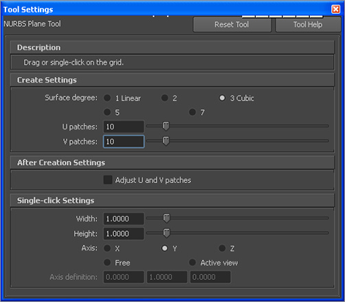
Figure 3-15: Options for creating the NURBS plane
The Universal Manipulator interactively shows you the movement, rotation, or scale as you manipulate the sphere. Notice the coordinates that come up and change as you move the sphere. When you rotate using this Manipulator, you see the degree of change. Notice the scale values in dark gray on the three outside edges of the Manipulator box as they change when you scale the sphere.
Next, let’s try using the Soft Modification tool (![]() ) from the Tool Box. This tool allows you to select an area on a surface or model and make any adjustments in an interesting way. The adjustments you make gradually taper off away from the initial place of selection, giving you an easy way to soft-modify an area of a model, like lifting up a tablecloth from the middle, for example. First, turn off Interactive Creation. To try the Soft Modification tool, create a NURBS plane by choosing Create ⇒ NURBS Primitives ⇒ Plane ❒. Doing so opens the options for creating a plane, as shown in Figure 3-15. Set both the U Patches and V Patches sliders to 10, and click Create.
) from the Tool Box. This tool allows you to select an area on a surface or model and make any adjustments in an interesting way. The adjustments you make gradually taper off away from the initial place of selection, giving you an easy way to soft-modify an area of a model, like lifting up a tablecloth from the middle, for example. First, turn off Interactive Creation. To try the Soft Modification tool, create a NURBS plane by choosing Create ⇒ NURBS Primitives ⇒ Plane ❒. Doing so opens the options for creating a plane, as shown in Figure 3-15. Set both the U Patches and V Patches sliders to 10, and click Create.
Click and drag a plane on the grid. (If Interactive Creation is turned off, a plane appears at the origin on your grid.) Select the Scale tool, and scale the plane up to about the size of the grid. Then, select the Soft Modification tool (![]() ) from the Tool Box, and click the plane somewhere just off the middle. Doing so creates an S and a special Manipulator to allow you to move, rotate, or scale this soft selection (see Figure 3-16). You also see a yellow-to-red-to-black gradient around the S manipulator. This shows you the area and degree of influence, where yellow moves the most and black the least.
) from the Tool Box, and click the plane somewhere just off the middle. Doing so creates an S and a special Manipulator to allow you to move, rotate, or scale this soft selection (see Figure 3-16). You also see a yellow-to-red-to-black gradient around the S manipulator. This shows you the area and degree of influence, where yellow moves the most and black the least.
Grab the cone handle, and drag it up to move the soft selection up. Notice that the plane lifts up in that area only, gradually falling off. This effect resembles what happens when you pick up a section of a tablecloth with one hand.
Grabbing the cube handle scales the soft selection, and dragging on the circle rotates it. After you’re done making your soft adjustments, you can go back to that soft selection by selecting the S on the surface for later editing. You can place as many soft selections as you need on a surface. Figure 3-17 shows the soft modification adjusting the plane.
Figure 3-16: Creating and manipulating a soft modification

Figure 3-17: Lifting an area of the NURBS plane

You can scale the Manipulator handles to make them more noticeable or less obtrusive. Press the plus key (+) to increase a Manipulator’s size, and press the minus key (–) to decrease it.
The Attribute Editor Window
To use the Attribute Editor, select Window ⇒ Attribute Editor (Ctrl+A). The Attribute Editor window is arguably the most important window in Maya. Every object is defined by a series of attributes, and you edit these attributes using the Attribute Editor. This window displays every attribute of an object, and you can use it to change them, set keyframes, connect to other attributes, attach expressions, or simply view the attributes.
Attribute Editor in a Floating Window
We’ll assume for the course of the book that you’ve set the Attribute Editor to open in its own window, as advised earlier in this chapter. Most figures reflect that assumption.
The Attribute Editor has tabs that correspond to the object’s node structure. You’ll learn more about Maya’s object structure later in this chapter, so don’t worry about what the tabs mean just yet. As you can see, each tab displays different attributes of the object.
Try This Press Ctrl+A to open the Attribute Editor for the sphere (shown in Figure 3-18), and click the makeNurbSphere1 tab.
Figure 3-18: The Attribute Editor
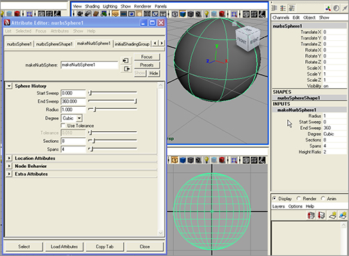
You’ll notice that the Channel Box now has the primary attributes (Translate X, Translate Y, Translate Z, Rotate X, and so on) of the sphere listed. Below them, you’ll find the shapes node named nurbsSphereShape1 and the inputs node makeNurbSphere1 listed. If you click the makeNurbSphere1 entry in the Channel Box, it will expand to show you Select attributes from the tab of the same name in the Attribute Editor. These attributes, despite being shown in two places, are the same. If you edit one in the Channel Box, it will be reflected in the Attribute Editor, and vice versa. The Channel Box is essentially a quick reference, giving you access to the most likely animated attributes of an object. The Attribute Editor goes into detail, giving you access to everything that makes up that object and the other nodes that influence it.
Figure 3-19: You can keep notes with an object’s attributes in the Attribute Editor.
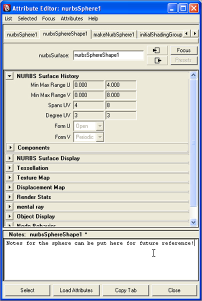
Try changing some of the settings in this window and see how doing so affects the sphere in the view panels. For example, changing the Radius attribute under the nurbsSphereShape1 tab changes the size of the sphere. Click the nurbsSphere1 tab next, and you’ll see the primary attributes listed. Try entering some different values for the Translate or Scale attributes to see what happens to the sphere in the view panels.
On the flip side, press W to activate the Move tool, and move the sphere around one of the view planes. Notice that the respective Translate attributes update in almost real time in both the Attribute Editor and the Channel Box. You’ll see an area for writing notes at the bottom of the Attribute Editor. This is handy because you can put reminders here of important events, such as how you set up an object or even a birthday or an anniversary. If you drag the horizontal bar, you can adjust the size of the notes space, as shown in Figure 3-19.
Because you’ll use the Attribute Editor constantly, you may want to keep the window open all the time and just move it around. You can also press the Ctrl+A hotkey to open the window more easily.
Outliner/Hypergraph
These two very different windows serve similar functions. They’re both used for organizing and grouping scene objects. These windows let you see every object node in your scene in either outline or flowchart/graph form.
When you’re well into an animation or a model, you’ll invariably have several elements in your scene. Without a roadmap, finding the correct object to select or manipulate can be difficult. Both windows provide this service.
How do you choose between the Outliner and the Hypergraph? It depends on exactly what you need to do. The Outliner is perfect for organizing, grouping objects, renaming nodes, and so forth. The Hypergraph displays all the connections between nodes, and it’s perfect for editing the relationships between nodes and locating hard-to-find nested nodes in a big scene.
The Outliner
To use the Outliner, select Window ⇒ Outliner (see Figure 3-20). It displays all the objects in your scene as an outline. You can select any object in a scene by clicking its name.
Figure 3-20: The Outliner

The objects are listed by order of creation within the scene, but you can easily reorganize them by MMB+clicking and dragging an object to a new location in the window; doing so lets you group certain objects in the list. This is a fantastic way to keep your scene organized.
Additionally, you can easily rename an object by double-clicking its Outliner entry and typing a new name. It’s crucial to an efficient animation process to keep things well named and properly organized. By doing so, you can quickly identify parts of your scene for later editing and troubleshooting.
A separator bar in the Outliner lets you split the display into two separate outline views. By clicking and dragging this bar up or down, you can see either end of a long list, with both ends having independent scrolling control.
The Hypergraph
By contrast, the Hypergraph: Hierarchy (referred to as just the Hypergraph from here on) displays all the objects in your scene in a graphical layout similar to a flowchart (see Figure 3-21). Select Window ⇒ Hypergraph: Hierarchy to see the relationships between the objects in your scene more directly. This window will perhaps be somewhat more difficult for a novice to decipher, but it affords you great control over object interconnectivity, hierarchy, and input and output connections. The Hypergraph Input and Output Connections window is technically called the Hypergraph window, but it shows you the interconnections of attributes among nodes as opposed to the layout of nodes and node hierarchy within the scene. For the most part, throughout this book we’ll be dealing with the Hypergraph Scene Hierarchy and referring to it as the Hypergraph.
Figure 3-21: The Hypergraph

Navigating the Hypergraph is the same as navigating any Modeling window using the familiar Alt key and mouse combinations for tracking and zooming. Subsequent chapters will focus much more on these two windows. Let’s have a quick look at the windows and their icons. Later, you can refer back to this section as needed.
Hypershade
Just as the Outliner and Hypergraph windows list the objects in the scene, the Hypershade window lists the textures and shaders of your scene. Shaders are assigned to objects to give them their visual appearance—their look and feel, in other words. Through the Hypershade, you can create and edit custom shaders and assign them to any object in the scene.
Maya uses render nodes to create shaders and shader networks for assignment to objects. Render nodes define the characteristics of shaders, which in turn are applied to objects to define how they will look when they’re rendered. Shader networks are complex shaders that rely on a network of render nodes to achieve special rendering or texturing effects.
The Hypershade (Window ⇒ Rendering Editors ⇒ Hypershade) displays the shaders and textures in your scene in a graphical flowchart layout similar to the Hypergraph window. (See Figure 3-22.) You can easily connect and disconnect render nodes to create anything from simple to complex shading networks. The Hypershade window has three main areas: the Create/Bins panel, the render node display, and the work area. The three icons at upper right let you easily switch views:
Figure 3-22: The Hypershade
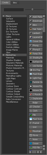
The Create/Bins Bar The Create/Bins bar or panel is divided into two tabs: Create and Bins, as shown in Figure 3-23. Selecting the Create tab gives you access to a variety of render nodes. The Bins tab adds a level of organization by letting you store sets of shaders in different bins to sort them. By default, Maya selects the Create tab. Here you can create any render node and its supporting textures by clicking the icon for the desired shader or texture. The bar at the top switches between Create Maya Nodes and Create Mental Ray Nodes. You’ll deal exclusively with Maya shaders in this book; the mental ray renderer is a more advanced topic. In the Create Maya Nodes panel, render nodes are divided into sections for their types, such as Surface (or material nodes), 2D Textures, Lights, and so on.
Figure 3-23: The Create/Bins bar
The Render Node Display Area After you create a render node, it appears in the display area as a thumbnail icon as well as in the work area and is available for editing. Clicking a render node’s icon selects that node for use. Double-clicking the icon opens the Attribute Editor. You can also use the middle mouse button to drag the icon to the work area, where you can create or edit the render node’s connections to other nodes to form shading networks. Navigating in this area of the Hypershade, as well as in the work area, is similar to navigating the Hypergraph and work windows in that you use the Alt/Option key and mouse controls.
The Work Area The work area is a free-form workspace where you can connect render nodes to form-shading networks that you can assign to your object(s) for rendering. This is by far the easiest place to create and edit complex shaders, because it gives you a clear flowchart of the network. You can add nodes to the workspace by MMB+clicking and dragging them from either the display area of the Hypershade or the Multilister window.
The Graph Editor
To use Maya’s Graph Editor, select Window ⇒ Animation Editors ⇒ Graph Editor. It’s an unbelievably powerful tool for the animator (see Figure 3-24), that you use to edit keyframes in animation.
Because 3D data is stored digitally as vector information in mathematical form, every movement that is set in Maya generates a graph of value versus time. The Graph Editor gives you direct access to the curves generated by your animation, which means you have unparalleled access to editing and fine-tuning your animation.
The Graph Editor is divided into two sections. The left portion, which is much like the Outliner, displays the selected objects and their hierarchy with a listing of their animated channels or attributes. By default, all of an object’s keyframed channels are displayed as colored curves in the display to the right of the list. However, by selecting an object or an object’s channel in the list, you can isolate only those curves that you want to see.
Figure 3-24: The Graph Editor
The Graph Editor displays these animation curves, also known as function curves, as value versus time, with value running vertically and time horizontally. Keyframes are represented on the curves as points that can be freely moved to adjust timing or value. You’ll want to tune and refine animation through the Graph Editor, because doing so gives you the utmost in control over value, timing, and finesse.
The concept of the Graph Editor, and the process of editing animation using graph curves, may seem daunting at first, especially if you aren’t mathematically inclined. However, this window is truly an animator’s best friend. Intimate knowledge of this process will come to you as you use the Graph Editor, and you’ll find it much easier to deal with animation. Most if not all animation programs make extensive use of a graph or a function-curve editor. You’ll be making significant use of the Graph Editor a little later on in the book.
The Script Editor
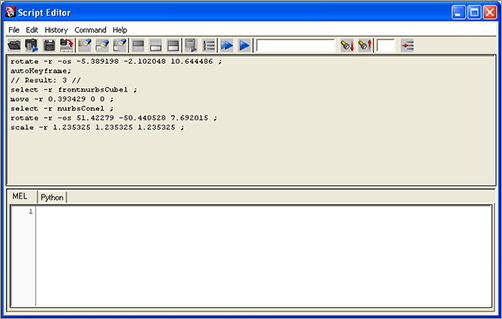
To use the Script Editor, select Window ⇒ General Editors ⇒ Script Editor. You can also access it (see Figure 3-25) by clicking the icon in the bottom-right corner of the screen at the end of the Command line or by choosing it from the menu. Because almost everything in Maya is built on MEL, every command you initiate generates some sort of MEL script or MEL argument. A history of these comments is available in the Script Editor.
This window is handy when you need to reference a command that was issued or an argument or a comment that was displayed. It’s also useful in scripting, or creating macros of MEL or Python commands to execute compound actions. When you want to create a custom procedure, you can copy and paste MEL from this window to form macros. You can also click the Python tab to switch to scripting in the popular Python language.
Figure 3-25: The Script Editor
The Script Editor is essential in learning how to script. However, scripting is a fairly advanced function that you may never need for your work. In any case, tackle scripting only after you establish a comfortable working repertoire in Maya.
The window has two halves. The top half is the Script Editor’s feedback history, and the bottom half is its Command line, where new MEL commands can be issued. By highlighting text in the upper window, you can copy and paste the command back into the Command line. You can easily add newly issued commands or macros of commands to the Shelf by choosing File ⇒ Save Script to Shelf or by clicking the Save Script to Shelf icon (![]() ) in the Script Editor’s top line.
) in the Script Editor’s top line.
Using the Script Editor is also a good way to check on error messages that are too long to view fully in the Command line’s Feedback box. If you see an error message pop up and something goes wrong, open the Script Editor to see what sort of error(s) have occurred.
The Connection Editor
To use the Connection Editor, select Window ⇒ General Editors ⇒ Connection Editor. You can use the Connection Editor (see Figure 3-26) to connect attributes between almost any two objects easily. Therefore, you can set up almost any sort of relationship between any number of objects. For example, the scale of a cube in the Y-axis could control the Y-axis rotation of a sphere through a simple click of the mouse to connect the two attributes. You can set up more complicated connections to rotate the tires of a car automatically as the car moves forward, for example.
Figure 3-26: The Connection Editor shows a newly created connection between a cone and a sphere.
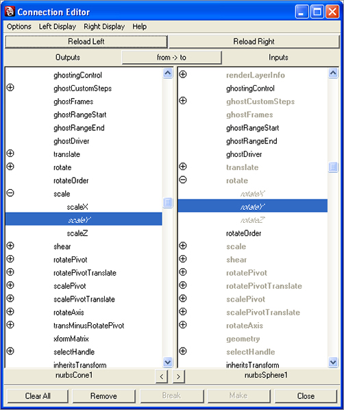
The Connection Editor window is separated into two vertical columns, each representing one of two objects. By selecting an object and clicking the Reload Left button, you can load all the attributes of the selected object into the Connection Editor’s left column. By selecting a second object and clicking Reload Right, you can load the attributes of the second object. Clicking attributes in both columns creates a direct relationship between the two objects’ attributes.
Connections are the cornerstone of animation and a significant reason for it being so open-ended in Maya. You can create any kind of relationship between almost any attributes of almost any object to create highly complex, interconnected animations as well as automate animations to simplify a job—and who wouldn’t want to simplify a job?
The Hotbox
The Hotbox gives you convenient access to Maya’s menus and commands. Figure 3-27 shows the Hotbox configured to show all the menus in Maya 2011.
Figure 3-27: The Hotbox and marking menus

To display the Hotbox, press and hold down the spacebar in any panel view. All the menu commands that are available from the Main menu bar are also available through the Hotbox. To access a command, simply click it. You can display some or all of the menu headings to give you quick access to whatever commands and features you use most by clicking Hotbox Controls and selecting the menus.
As you can see in Figure 3-27, the Hotbox is separated into five distinct zones—North, East, West, South, and Center—delineated by black diagonal lines. Activating the Hotbox and clicking a zone displays a set of shortcut menu commands called marking menus, discussed in the next section.
If you don’t see all the menu options when you invoke the Hotbox, or if you want to restrict the menu display to specific menu sets, simply invoke the Hotbox by pressing the spacebar, click Hotbox Controls, and mark the selection of menus you would like, such as Hide All or Show All, from the marking menu.
Marking Menus
In addition to menu selections, the Hotbox has marking menus in each of the five zones. Using marking menus is yet another way to quickly access the commands you use the most. By default, the marking menus deal with changing your selection masks (which objects you can and can’t select), Control Panel visibility, and the type of panel that is being displayed. You can also access predefined (but customizable) key/mouse strokes through the Hotbox.
A Word to the Wise about the Hotbox
You should use the Hotbox/marking menus only when you’re comfortable with the interface and you’ve begun to establish a workflow for yourself. After you begin using them, however, you’ll find them pleasantly efficient. Many animators prefer to turn off the menu bar to increase screen space for modeling and animating, and use the Hotbox exclusively. Others use both.
Again, use the Main Menu bar at the top of the screen instead of the Hotbox when you’re learning. It’s better to find out where the commands are first. It also helps cut down the clutter of commands and potential confusion about where and how to find them.
Menu Sets
Recall that menu sets are organized according to function. These menu sets are Animation, Polygons, Surfaces, Dynamics, Rendering, and nDynamics. Each menu set gives you access to the commands associated with its broader function set. The Animation menu set, for example, displays in the Main Menu bar all the menu headers that correspond to animation functions, such as the Deform and Skeleton menus.
The Menu Set drop-down is the first thing on the Status line, as shown in Figure 3-28.
Figure 3-28: The menu sets help organize the menu headings.

Changing between menus is easier if you use the default hotkeys:
| Key | Function |
| F2 | Animation menu set |
| F3 | Polygons menu set |
| F4 | Surfaces menu set |
| F5 | Dynamics menu set |
| F6 | Rendering menu set |
Switching back and forth between menu sets may feel a little strange at first, but it makes for a much more organized workspace than having all the menu headers staring at you across the top of the window as you animate. Besides, you can access all the functions through the Hotbox anywhere on the screen.
When you’re wondering where a particular toolset is, all you need to do is ask yourself, “What CG phase would that function fall under?” Because the menu sets are organized in phases of computer animation workflow—modeling (Polygons and Surfaces), animating, dynamics, and lighting/rendering—the task dictates which menu includes its toolset.