
The Production Process: Creating and Animating the Objects
As discussed in Chapter 1, “Introduction to Computer Graphics and 3D,” production is typically divided into phases to make workflow easier to manage. In this project, you’ll first create the Sun, the planets, and their moons; then, you’ll animate their respective orbits and rotations.
Creating the Sun and the Planets
The first thing you’re going to do is create the Sun and the planets. Follow these steps:
1. Choose File ⇒ New Scene (or press Ctrl+N). Maya asks if you want to save your current scene. Save the file if you need to, or click Don’t Save to discard the scene.
2. By default, Maya’s screen should begin in an expanded perspective view. Press the spacebar to enable the four-panel view. When you’re in the four-panel view, press the spacebar with the cursor inside the top view panel to select and maximize it.
Figure 2-6: Turning off Interactive Creation

3. To create the Sun, you need a primitive sphere. A primitive is a basic 3D shape. First, let’s turn off a Maya feature called Interactive Creation that is on by default. Turning off Interactive Creation allows you to create the sphere at the center of the grid (the origin) without having to click and drag its size and then reposition it manually. Uncheck Create ⇒ NURBS Primitives ⇒ Interactive Creation to toggle it off, as shown in Figure 2-6. For more on how to create primitives with interactive feedback, see the section on primitives in Chapter 3.
4. With Interactive Creation turned off, choose Create ⇒ NURBS Primitives ⇒ Sphere. Doing so places a NURBS sphere exactly at the origin—that is, at a position of 0,0,0 for X,Y,Z. This is good, because the origin of the workspace will be the center of the Solar System, too.
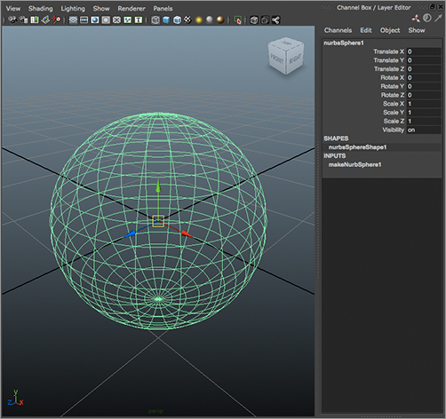
5. Select the word nurbsSphere1 in the Channel Box to the right of the Maya UI (shown in Figure 2-7), and enter Sun to rename it. If you don’t see the Channel Box in your Maya window, please refer to the section on the Channel Box in Chapter 3.
NURBS and Polygons
NURBS and polygons are two types of geometry that you can create and edit in Maya. We’ll explore the uses of each modeling type in Chapter 4, “Beginning Polygonal Modeling,” Chapter 5, “Modeling with NURBS, Subdivisions, and Deformers, and Chapter 6, “Building the Red Wagon.”
Figure 2-7: Renaming the sphere in the Channel Box
Always keep in mind that Maya is case sensitive. An object named “sun” is different from an object named “Sun.”
Naming your objects right after creation is a good habit to develop. Doing so makes for a cleaner scene file and a more organized workspace. This is particularly important if anyone needs to alter your scene file; proper naming will keep them from getting frustrated when they work on your scene.
Maya typically uses an object-naming structure called a humpback style, where words are slung together without spaces. The first letter of a new word in the humpback name is capitalized. An example of humpback style is the name indoorPatioScene. Maya uses this structure when naming nodes, such as the node name nurbsSphere1.
6. Choose the Scale tool in the Tool Box to activate the Scale Manipulator, and uniformly scale the Sun sphere up to about four times its creation scale of 1. (Make it a scale of about 4 in all three axes.) For more precision, you can do one of two things: You can select the sphere and enter a value of 4 in all three entry fields (the white window next to the attribute) for the Scale X, Scale Y, and Scale Z channels in the Channel Box shown in Figure 2-8. Alternatively, you can enter a value of 4 in the Input box on the Status line along the top of the UI, as shown here. Don’t worry; we’ll take an in-depth look at both of these methods in the next chapter.
Figure 2-8: The Sun’s Scale values in the Channel Box
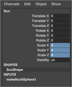
7. After you enter the final value through either method, press Enter, and the sphere will grow to be four times its original size (at a scale of 1). When you enter the values in either the Channel Box or the Input box, a scale of 4 appears in all three fields, as shown in Figure 2-8, and your Sun expands in size by a factor of 4. Entering exact values in the Channel Box or Input box is a way to scale the sphere precisely; using the Manipulator isn’t as precise.
Creating the Planets
Next, you’ll create the primitive spheres you’ll be using for the planets. Leave Interactive Creation off, and follow these steps:
1. Create a NURBS sphere for Mercury just as you did before, by choosing Create ⇒ NURBS Primitives ⇒ Sphere. A new sphere appears at the origin. Click its name in the Channel Box, and change it to Mercury.
2. Choose the Move tool from the Tool Box to activate the Move Manipulator, and move Mercury a few grid units away from the Sun in the positive X direction. (Click the red arrow and drag it to the right.) Leave about two grid units between Mercury and the Sun.
3. Because Mercury is the second smallest planet and is tiny compared to the Sun, scale it down to 1⁄20 the size of the Sun, or type in 0.2 in all three axes of scale if you choose to enter the values manually in the Channel Box.
4. Repeat steps 1 through 3 to create the rest of the planets and line them up, placing each one farther out along the X-axis. Be sure to keep about two grid units of space between them. Scale each one proportionally as follows:
| Venus | 0.5 |
| Earth | 0.5 |
| Mars | 0.4 |
| Jupiter | 1.0 |
| Saturn | 0.9 |
| Uranus | 0.7 |
| Neptune | 0.7 |
| Pluto | 0.15 |
These proportions aren’t exactly the same as those found in the real Solar System, but they will do nicely here. Figure 2-9 shows how your Solar System should look now.
Figure 2-9: All the NURBS spheres are lined up in place (top view).

No, Pluto isn’t actually a planet anymore, but for nostalgia’s sake, we’ll include it here in our Solar System. Poor Pluto!
Using Snaps
Now is the perfect time to start using snaps. Some common snap icons are shown in Table 2-1. Snap icons are explained in greater depth in the next chapter. These icons run across the top of the UI just below the Main Menu bar, as shown here.
Snap Icons
| Snap Icon | Name | Description |
|
|
Snap to Grids | Snaps objects to intersections of the view’s grid |
|
|
Snap to Curves | Snaps objects along a curve |
|
|
Snap to Points | Snaps objects to object points such as CVs or vertices |
|
|
Snap to View Planes | Snaps objects to view planes |
You use snaps to snap objects into place with precision, by placing them by their pivot points directly onto grid points, onto other object pivots, onto curve points, and so on. Here you’ll reposition all the planets slightly to center them on the nearest grid line intersection. To do so, follow these steps:
1. Select the first planet, Mercury. Choose the Move tool from the Tool Box, and toggle on ![]() ).
).
2. The center of the Move Manipulator turns from a square to a circle, signaling that some form of snapping is active. Grab the Manipulator in the middle by this circle, and move it slightly to the left or right to snap it onto the closest grid intersection on the X-axis.
3. Select the remaining planets, and snap them all to the closest grid intersection on the X-axis, making sure to keep about two grid spaces between each of them. Because the Sun was created at the origin and you haven’t moved it, you don’t need to snap it onto an intersection.
Saving Multiple Versions of Your Work and Incremental Saving
As you’re working on a project, you may want to save multiple versions of your files at various stages of completion. When working in the professional world, you’ll find that clients and art directors often reconsider animations you’ve created, sometimes, it seems, just to make you crazy. So, it’s always good to keep as many versions of an animation as you can. Scene files are reasonably small, and hard disk space is inexpensive. Just keep your Scene folder organized well—for example, by keeping older versions of scenes in separate subfolders—and you should have no problems.
Maya’s Incremental Save feature makes a backup of your scene file every time you save your scene. To enable it, choose File ⇒ Save Scene ❒, and click the Incremental Save box. After you’ve done this, Maya will create a new folder within your Scenes folder with the name of your current scene file. It will then create a backup of your scene in that folder and append a number to the filename: for example, planets_001.mb. Every time you save your file, Maya will create a new backup until you disable the feature by choosing File ⇒ Save Scene ❒.
The scene files for the projects in this book are provided on the accompanying CD to give you a reference point for the major stages of each project. These files use a slightly different naming system than the names generated by Incremental Save (for example, the file on the CD is planets_v1.mb instead of planets_001.mb), so there is no risk of files overwriting each other.
For important real-world projects, you may decide to supplement the Incremental Save backups by using Save Scene As to create named files manually, perhaps following a similar naming system with a version number appended, at the stages where you’ve made significant changes. Whether you do this or use Incremental Save, it’s a good idea to keep written notes about the differences in each version of a scene file so that whenever you make a significant change to a file, you have a record of your work.
If you prefer to name files manually, be sure to use an underscore (_) between the filename and version number instead of a space. Using spaces in your filenames can create problems with the software and operating system, especially when you’re rendering out a scene.
Making Saturn’s Ring
Now, create the ring for Saturn. To do so, follow these steps:
1. Choose Create ⇒ NURBS Primitives ⇒ Torus to place a donut shape at the origin. Remember, Interactive Creation is turned off. You can also try creating the torus with the Interactive Creation option. In that case, click and drag the mouse to create the donut shape as you prefer. When you have a ring, use the Move tool to snap it to the same grid intersection as Saturn. This ensures that both the planet and its ring are on the same pivot point and share the same center.
2. Select the torus shape you’ve created, and name it Ring (if you haven’t already done so) in the Channel Box.
3. While the torus shape is still selected in the top view, press the spacebar to display the four-panel layout. Place the mouse cursor in the persp view, and press the spacebar to maximize the Perspective window.
Figure 2-10: Changing the creation attributes of the NURBS torus in the Attribute Editor

4. Press the F key to focus the perspective display on the ring and on Saturn. Pressing F centers and zooms in the panel on just the selected object(s).
5. Press 5 to get into Shaded mode, and, with the torus selected, press 3 to increase the resolution display for the ring. Display resolutions are achieved by pressing the 1, 2, or 3 key and are further explained in the next chapter. Pressing 3 gives you the smoothest view of the torus in the view panels. That’s a good thing.
6. From the Tool box, select the Scale tool, and scale the torus down to 0 or close to 0 in the Y-axis (the torus’s height, in this case) to flatten it.
You’ll notice that the ring is too fat and is cutting into the planet. You need to edit the attributes of the ring to increase the inside radius of the donut shape and create a gap between the planet and the ring.
7. Press Ctrl+A (Ctrl+A will also work on a Mac) to toggle the Attribute Editor if it’s not on, and then click the makeNurbTorus1 tab to select its creation node. (See Figure 2-10.)
8. Increase the Radius attribute to about 1.5, and decrease the Height Ratio attribute to about 0.25 to get the desired effect.
Now all your planets are complete, and you can move on to the moons.
Changing the original attributes or parameters of an object, as you’ve just done with Saturn’s ring, is often referred to as parametric modeling.
Saving Your Work
Save your work, unless you like to live on the edge. Saving frequently is a critical habit to develop. Power failures and other unforeseen circumstances (such as your pet jumping onto your keyboard) may not happen often, but they do happen, and usually at the wrong time. (As mentioned in the sidebar “Saving Multiple Versions of Your Work and Incremental Saving,” Maya’s Incremental Save feature makes it easy to maintain backups of your work.) Because you created this as a new project, the Save File window will direct you to the Scenes folder of that project. Save your scene as planets in the .mb (Maya Binary) format. (If you’re working in Maya PLE, you can only save your files as .mp files, which may not be compatible with full versions of Maya 2011. Maya PLE saves scenes as .mp files simply to differentiate them from full Maya-version saved files.)
The file Planets_v1.mb in the Scenes folder of the Solar_System project on the CD shows what the scene should look like at this point.
Creating the Moons
For the planets with moons, create a new NURBS sphere for each moon. For simplicity’s sake, create a maximum of only two moons for any planet. However, feel free to make all the moons for all the planets after you get a handle on this exercise.
The first moon will be Earth’s. Use the top view to follow these steps:
1. Create a NURBS sphere, and scale it to about half the size of Earth using the Scale tool. Visually estimate the size of the moon.
2. Move the sphere to within half a unit of Earth, using the Move tool by the ![]() ).
).
3. Repeat steps 1 and 2 for the remaining moons, placing them each within half a grid unit from their respective planets. When placing two moons, place them on opposite sides of the planet.
4. After you’re done with all the moons, their placements, and their sizes, select all the elements in the scene and press 3 to increase the display resolution on all the spheres. This gives you a smoother view of the NURBS spheres. When you’re finished, you should have a scene similar to Figure 2-11 in perspective view. If you don’t, it’s clear Maya doesn’t like you.
Figure 2-11: The planets and moons in position in perspective view

Applying a Simple Shader
To help distinguish one gray planet from another, attach simple shaders to each of the planets to give them color. You can easily take care of this task using the Hypershade window. Follow these steps:
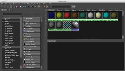
1. Choose Window ⇒ Rendering Editors ⇒ Hypershade to open the Hypershade window. This window lists and allows you to edit all the shaders and textures in the scene. With this window, you create the look of your objects by assigning colors, surface properties, and so on. You’ll notice three default (or initial) shader icons already loaded. (See Figure 2-12.) For more on the Hypershade window, see Chapter 3.
Figure 2-12: The Hypershade window

2. In the Create Maya Nodes panel on the left of the Hypershade window and under the Surface heading, click the Lambert icon (a gray sphere) to create a new Lambert shader node. It appears in the top and bottom of the Hypershade window. Click this icon eight more times to create a total of nine Lambert shading groups in the Hypershade window.
3. Click the first of the new Lambert nodes (lambert2) in the Hypershade window, and you should notice its attributes display in the Attribute Editor on the right of the UI. If you have the Channel Box displayed instead, double-click the shader’s icon to open the Attribute Editor. At the top, replace lambert2 with Mercury_Color to identify this material as the one you’ll use for Mercury.
4. Name each of the remaining planets in your animation (Venus, Earth, Mars, Jupiter, Saturn, Uranus, Neptune, and Pluto).
To rename a node in the Hypershade window, you can also right-click the node’s icon and choose Rename from the shortcut menu that appears.
Again, keeping a well-named and organized scene is critical to a smooth animation experience. It’s much more of a chore to root through dozens of unnamed nodes to find the one you want. When you’ve finished naming all the material nodes, save your work.
After you’ve created the shaders, you can assign the appropriate colors to each of them according to the planet they represent:
1. Double-click Mercury to open its Attribute Editor, if it’s not currently open (see Figure 2-13).
2. To change the color of the shader, click the gray box next to the Color attribute. This opens the Color Chooser window, where you can choose a new color from the color wheel or by adjusting values with the HSV sliders. Because Mercury has a brownish red appearance, go with an orange color, such as in Figure 2-14 (take note of the HSV values).
Figure 2-13: Mercury’s shading group in the Attribute Editor
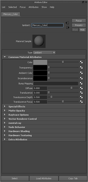
Figure 2-14: The Color Chooser window

Setting Keyframes


As with many other functions in Maya, you can set a keyframe in several ways. Switch to the Animation menu set by pressing F2. When you’re first starting to learn Maya, the best way is to choose Animate ⇒ Set Key ❒ to display the Set Key Options dialog box. Here, you’re selecting the Option box for that menu item by clicking the little empty box to the right of the menu item. The Option box for any particular menu item allows you to set the options for that function. In this case, you’re changing the options for the Set Key function.
If you choose Animate ⇒ Set Key without first changing those options, Maya sets a keyframe for all the keyable attributes for the selected object. Although this may seem convenient, it makes for a sloppy scene, especially if the scene must be heavily animated.
Having keyframes for attributes that may not actually be animated creates unnecessary clutter. In the Set Key Options dialog box shown here, set the Set Keys On option to All Keyable Attributes instead of the default All Manipulator Handles and Keyable Attributes. Set Channels to From Channel Box instead of the default All Keyable. (These attributes will remain grayed out until you change to All Keyable Attributes.) Now, when you choose Animate ⇒ Set Key, you’ll set a keyframe only for the channels that you specify explicitly through the Channel Box, giving you greater control and efficiency. All you have to do is highlight the channel you want to keyframe in the Channel Box and then choose Animate ⇒ Set Key. Save your settings by choosing Edit ⇒ Save Settings, and then click Close to close the dialog box.
3. Change the remainder of the shaders as follows:
| Mercury | Orange-brown |
| Venus | Beige-yellow |
| Earth | Blue |
| Mars | Red-orange |
| Jupiter | Yellow-green |
| Saturn | Pale yellow |
| Uranus | Cyan |
| Neptune | Aqua blue |
| Pluto | Bright gray |
Figure 2-15 shows the shading groups.
Figure 2-15: The Hypershade window with all the colored planet shading groups
4. Next, apply shaders to the planets. Select a planet in the Perspective window, and right-click its corresponding material in the Hypershade window to open a marking menu. Drag up to highlight Assign Material to Selection, and release the button to select it. You can also use the middle mouse button to drag the material from the Hypershade window to its planet. Leave the moons set to the default gray color. When you’re finished, you should have a scene similar to Figure 2-16.
Figure 2-16: The shaded planets in perspective view

Now that you’re finished, you’re ready to animate. Save this file; if you enabled Incremental Save as recommended earlier, your file won’t be replaced with subsequent saves. This way, if you get lost in your animation and need to start fresh, you won’t have to re-create everything from scratch. You can return to a previous version of the file and start your animation over.
Creating the Animation
To begin this phase of the project, load the file Planets_v2.mb in the Scenes folder of the Solar_System project on the CD to your hard drive, or continue with your own scene file.
The animation you’ll do for the orbits is straightforward. You’ll rotate the planets around their own axes for their self-rotation, and then you’ll animate the moons around the planets for their lunar orbits, and finally you’ll make the planets and their moons orbit the Sun.
The premise of this exercise deals with hierarchy and pivot points. A pivot point is an object’s center of balance of sorts. Every object or node that is created in Maya has a pivot point set at the origin. Because most objects, such as the spheres you created for the planets, appear at the origin upon creation, their pivot points are automatically centered.
When you move an object, as you’ve done to position the planets and moons, the pivot point moves with it. Therefore, all your planets’ and moons’ pivot points are already correctly positioned at the center of each planet and moon.
Now, you need to set up your scene file’s animation settings:
1. Press F2 to open the Animation menu set. Menu sets are groupings of menu headings in the Main Menu bar. They’re organized according to the type of task at hand. You’ll see the first several menu headings change when you switch from one menu set to another.
2. At the bottom of the UI, you’ll notice a slider bar (the Range slider) directly below the strip of numbers counting off the frames (the Time slider) in the scene. Using the Range slider, you’ll set the length of your animation to go from 1 to 240. Enter 1 in the Scene Start Frame and Range Start Frame boxes (Figure 2-17). Enter a value of 240 in the Scene End Frame and Range End Frame boxes, also as called out in Figure 2-17.
Figure 2-17: The Time and Range sliders
3. To the right of the Range slider, click the Animation Preferences icon (![]() ) (shown here in the context of the lower-right corner of the Maya screen), click Settings, and set Time to NTSC (30fps), which is 30 frames per second, or NTSC video speed. Also see Figure 2-18.
) (shown here in the context of the lower-right corner of the Maya screen), click Settings, and set Time to NTSC (30fps), which is 30 frames per second, or NTSC video speed. Also see Figure 2-18.
Figure 2-18: Set Time to 30fps in the Settings tab of the Preferences window.

4. Also verify that Up Axis is set to Y and not Z, as shown in Figure 2-18. This ensures that you’ve designated the Y-axis to be pointing “up” in the perspective window or pointing out at you from the monitor in the top view. Y up, as it’s called, is Maya’s default, but it never hurts to make sure, especially if you’re on a shared computer.
Choose Window ⇒ Settings/Preferences ⇒ Preferences to open the Preferences window. Under Settings: Undo, make sure Undo is on (if it isn’t already), and set Queue to Infinite. Setting Queue to Infinite takes a little more system memory, but it’s worth it. With this configuration, you can undo (press Ctrl+Z, Command+Z, or just Z if you’re using a Mac) as many times as it takes to undo any blunders. To close the Preferences window, click Save.
Mercury’s Rotation
Now you’re ready to animate Mercury’s rotation. Follow these steps:
1. Select Mercury, and press E to activate the Rotate tool. The E key is the hotkey to invoke the Rotate tool in Maya; pressing it is the same as clicking the Rotate Tool icon in the Tool Box, as you’ve been doing so far. Press F to focus on Mercury in the perspective view, or zoom in on it manually.
2. Make sure you’re on frame 1 of your animation range by clicking and dragging the Scrub bar (refer back to Figure 2-17) to place it at the desired frame. You can also manually type the frame value of 1 in the Current Frame box.
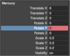
3. For Mercury, you’ll set your initial keyframe for the Y-axis rotation. Click the Rotate Y’s attribute name in the Channel Box to select it (it’s then highlighted in gray, as shown in Figure 2-19), and, in the Main Menu bar, choose Animate ⇒ Set Key. This places a keyframe for a rotation of 0 in the Y-axis at frame 1 for the Mercury sphere. If you followed the advice in the sidebar “Setting Keyframes,” earlier in this chapter, only the Rotate Y attribute’s Value box turns from white to orange to indicate that a keyframe exists for that attribute. If you left the Set Key command at its defaults, choosing Animate ⇒ Set Key sets keys on all the attributes for the sphere, turning all their values orange in the Channel Box.
Figure 2-19: Setting the initial keyframe for Mercury’s Y-axis rotation
4. Using the Scrub bar in the Time slider, go to frame 240. Grab the Rotation Manipulator handle by the Y-axis (the green circle), and turn it clockwise a few times to rotate the sphere clockwise. You’ll notice that you can rotate the object only so far in one direction before it seems to reset back to its original starting rotation. Rotate it as far as it will go, and release the mouse button. Then, click the Manipulator again, and drag to rotate the sphere as many times as necessary until you’re satisfied.
5. Choose Animate ⇒ Set Key with the Rotate Y attribute still selected in the Channel Box. This sets a keyframe for the new Y-axis rotation at frame 240 for the Mercury sphere.
6. To play back your animation, you can scrub your Time slider. Scrubbing is using the mouse to move the Scrub bar back and forth so you can watch the animation play back in a window. Click in the Time slider on the Scrub bar, hold down the left mouse button, and move your cursor from side to side to scrub in real time. You see Mercury rotating in your active view panel, if you set your two keyframes as described.
Clicking so many things just to set two keyframes may seem like a lot of work, but you’re doing this the long way right now; you’re not yet using any shortcuts or hotkeys. You’ll start using those for the next planet.
You have the self-rotation for Mercury worked out. Mercury has no moon, so let’s get Mercury orbiting the Sun.
Grouping Mercury for a New Pivot Point
You’ve learned that every object in Maya is created with a pivot point around which it rotates, from which or to which it scales, and which acts as the placement point for its X-, Y-, and Z-coordinates. To orbit Mercury around the Sun, the sphere must revolve around a pivot point that is placed in the middle of the Sun. If the pivot point for Mercury is already at the center of itself, how can you revolve it around the Sun?
One idea is to move its current pivot point from the center of itself to the center of the Sun. That would, however, negate Mercury’s own rotation, and it would no longer spin around its own center, so you can’t do that. You need to create a new pivot point for this object. This way, you have the original pivot point at Mercury’s center so it can self-rotate, and you have a second pivot point at the Sun so that Mercury can revolve around that point around the Sun. You’ll accomplish this by creating a new parent node above Mercury in the hierarchy. What does that mean?
In order not to get too confusing, we’ll take time in the following section to introduce the concept of Maya object structure: nodes and hierarchies. Save your progress so far, and open a new blank scene. After this explanation, we’ll resume the Solar System exercise.