
NURBS modeling depends on surfaces that are created using curves. Just as control vertices (CVs) are connected to form curved lines, NURBS surfaces are created by connecting (or spanning) curves. Therefore, typical NURBS modeling pipelines first involve the creation of curves that define the edges, outline, paths, and/or boundaries of surfaces.
When a surface is created, its shape is defined and governed by its isoparms. These surface curves, or curves that reside solely on a surface, show the outline of a surface’s shape much as the chicken wire in a wire mesh sculpture does. CVs on the isoparms define and govern the shape of these isoparms just as they would regular curves. Adjusting a NURBS surface involves manipulating the CVs of the object, somewhat like sculpting.
You can create a NURBS surface in several ways. The easiest way is to create a NURBS primitive. You can sculpt the primitive surface by moving its CVs, but you can also cut it apart to create different surface swatches or patches to use as needed, which you’ll see in a steam pump model for the locomotive later in this chapter. A primitive need not retain its original shape, and it frequently can be shaped to fit the artist’s needs. Using the surfacing tools available under the Surfaces menu set, you can detach, cut, and attach pieces into and out of a primitive to get the exact shapes you need.
You can also make surfaces in several ways without using a primitive. All these methods involve first creating or using existing NURBS curves, or curves on another surface, to define a part or parts of the surface, and then using one of the methods described in the following sections to create the surfaces.
Lofting
The most common surfacing method is lofting, which takes at least two curves and creates a surface span between each selected curve in the order in which they’re selected. Figure 5-1 shows the result of lofting two curves together.
Figure 5-1: A simple loft created between two curves
To create a loft, follow these steps:
1. Switch to the Surfaces menu set (press F4).
2. Draw the two curves.
3. Select the curves in the order in which you want the surface to be generated.
4. Choose Surfaces ⇒ Loft, or click the Loft icon in the Surfaces shelf (![]() ).
).
Figure 5-2: A loft created with four curves that are selected in order from left to right
When you define more curves for the loft, Maya can create more complex shapes. The more CVs for each curve, the more isoparms you have, and the more detail in the surface. Figure 5-2 shows how four curves can be lofted together to form a more complex surface. You can use almost any number of curves for a lofted surface.
Lofting works best when curves are drawn as cross-sectional slices of the object to be modeled. Lofting is used to make a variety of surfaces, which may be as simple as tabletops or as complex as human faces.
Revolved Surface
A revolved surface requires only one curve that is turned about a point in space to create a surface, like a woodworker shaping a table leg on a lathe. First you draw a profile curve to create a profile of the desired object, and then you revolve this curve (anywhere from 0 degrees to 360 degrees) around a single point in the scene to create the surface. The profile revolves around the object’s pivot point, which is typically placed at the origin but can be moved (as seen in the Solar System exercise in Chapter 2, “Jumping in Headfirst, with Both Feet”), and sweeps a new surface along its way. Figure 5-3 shows the profile curve for a wine glass.
The curve is then revolved around the Y-axis a full 360 degrees to create the wine glass. Figure 5-4 is the complete revolved surface with the profile revolved around the Y-axis.
To create a revolved surface, draw and select your profile curve, and then choose Surfaces ⇒ Revolve.
Figure 5-3: A profile curve is drawn in the outline of a wine glass in the Y-axis.
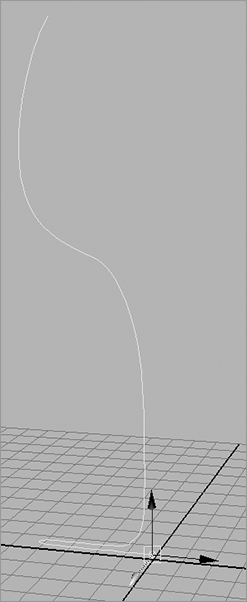
Figure 5-4: The revolved surface
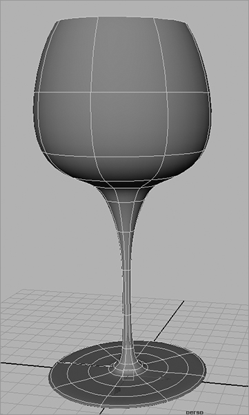
A revolved surface is useful for creating objects such as bottles, furniture legs, and baseball bats—anything that is symmetrical about an axis.
Extruded Surface
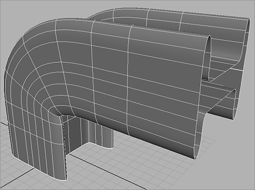
An extruded surface uses two curves: a profile curve and a path curve. The profile curve is drawn to create the profile shape of the desired surface. It’s then swept from one end of the path curve to its other end, creating spans of a surface along its travel. The higher the CV count on each curve, the more detail the surface will have. An extruded surface can also take the profile curve and simply stretch it to a specified distance straight along one direction or axis, doing away with the profile curve. Figure 5-5 shows the profile and path curves, and Figure 5-6 shows the resulting surface after the profile is extruded along the path.
Figure 5-5: The profile curve is drawn in the shape of an I, and the path curve comes up and bends toward the camera.
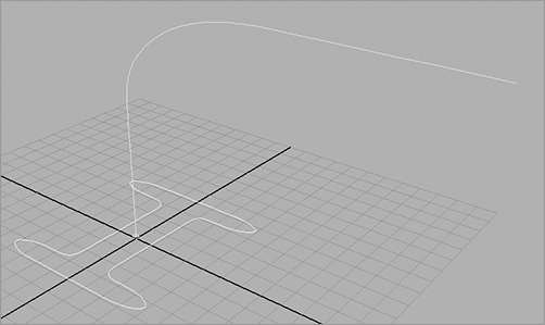
Figure 5-6: After extrusion, the surface becomes a bent I-beam.
To create an extruded surface, follow these steps:
1. Draw both curves.
2. Select the profile curve.
3. Shift+click the path curve.
4. Choose Surfaces ⇒ Extrude.
An extruded surface is used to make items such as winding tunnels, coiled garden hoses, springs, and curtains.
Planar Surface
A planar surface uses one perfectly flat curve to make a two-dimensional cap in the shape of that curve. It does this by laying down a NURBS plane (a flat, square NURBS primitive) and carving out the shape of the curve like a cookie cutter. The resulting surface is a perfectly flat, cutout shape, also known as a trimmed surface because the “excess” outside the shape curve is trimmed away.
To create a planar surface, draw and select the curve and then choose Surfaces ⇒ Planar.
You can also use multiple curves within each other to create a planar surface with holes in it. A simple planar surface is shown on the left side of Figure 5-7. When a second curve is added inside the original curve and both are selected, the planar surface is created with a hole. On the right side is the result when the outer curve is selected first and then the inner curve is selected before Surfaces ⇒ Planar is chosen.
Figure 5-7: A planar surface based on a single curve (left). A planar surface based on a curve within a curve to create the cutout (right).

A planar surface is great for flat lettering, for pieces of a marionette doll or paper cutout, or for capping the ends of a hollow extrusion. Planar surfaces are best left as flat pieces, however, because deforming them may not give the best results. In addition, it’s sometimes best to create the planar surface as a polygon. You’ll see how to convert surfaces to polygons later in this chapter. The following quick exercise will give you an idea of what to look out for when creating polygons from surfacing techniques:
1. In the Surfaces menu set, select Create ⇒ NURBS Primitives ⇒ Circle twice to create two circles.
2. Scale the second circle to about three times its original size, as shown in Figure 5-8.
3. Select the larger circle first, then the smaller circle, and finally select Surfaces ⇒ Planar ❒. In the option box, check Polygons for Output Geometry, Quads for Type, and General for Tessellation Method, as shown in Figure 5-9.
Figure 5-8: Scale the circle up.
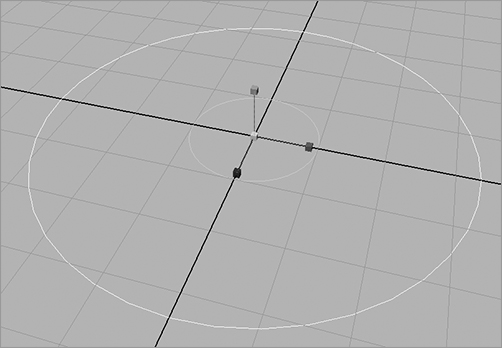
Figure 5-9: Choose these options.

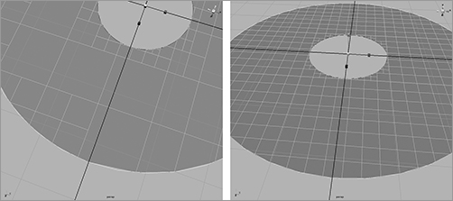
4. Depending on how you create the geometry as polygons, you’ll get different results—particularly around curves. Because Maya has to figure out where to put more faces to create a smoother outline, you have to set the Number U and Number V settings to best fit the curves of your resulting surface. At the current settings, your planar surface looks as shown in Figure 5-10. Notice the small gaps between the original outer NURBS circle and the surface outline.
5. Increase the Number U and Number V values, and you’ll get tighter results at curves, although you’ll have more faces on your model.
Figure 5-10: Notice the gaps between the outer NURBS circle and the outline.
Keep this exercise in mind as you continue modeling. Whenever you need to create polygons from NURBS surfaces, which should be quite often for some people, try the different creation methods for the best output. No one way works best all the time.
If you try creating a planar surface using a curve and notice that Maya doesn’t allow it, verify that the curve(s) is perfectly flat. If any of the CVs aren’t on the same plane as the others, the planar surface won’t work.
Beveled Surface
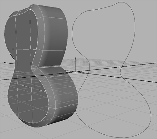
The Bevel Surface function takes an open or a closed curve and extrudes its outline to create a side surface. It creates a bevel on one or both corners of the resulting surface to create an edge that can be made smooth or sharp (see Figure 5-11). The many options in the Bevel tool allow you to control the size of the bevel and depth of extrusion, giving you great flexibility. When a bevel is created, you can easily cap the bevel with planar surfaces.
To create a bevel, draw and select your curve, and then choose Surfaces ⇒ Bevel.
Figure 5-11: A curve before and after it’s beveled. The beveled surface has been given a planar cap.
Maya also offers a Bevel Plus surface, which has more creation options for advanced bevels. A beveled surface is great for creating 3D lettering, for creating items such as bottle caps or buttons, and for rounding out an object’s edges.
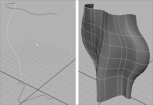
Boundary Surface
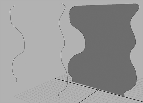
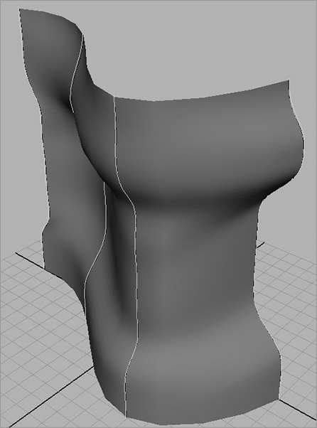
A boundary surface is so named because it’s created within the boundaries of three or four surrounding curves. For example, two vertical curves are drawn opposite each other to define the two side edges of the surface. Two horizontal curves are then drawn to define the upper and lower edges. These curves can have depth to them; they need not be flat for the boundary surface to work, unlike a planar surface. Although you can select the curves in any order, it’s best to select them in opposing pairs. In Figure 5-12, four curves are created and arranged to form the edges of a surface to be created. First, select the vertical pair of curves, because they’re opposing pairs; then, select the second two horizontal curves before choosing Surfaces ⇒ Boundary.
A boundary surface is useful for creating shapes such as car hoods, fenders, and other formed panels.
Figure 5-12: Four curves arranged to create the edges for a surface (left). The resulting boundary surface formed from the four curves (right).
Combining Techniques
You can use certain surfacing techniques in combination to create intricate models. For example, whenever a curve is required for a surface, you can use an isoparm instead to create a surface between two existing surfaces.
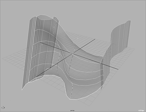
Try This Take a couple of lofted surfaces, and connect them with a third surface. Figure 5-13 shows two surfaces with two intermediate curves between them. (Notice that the view panel’s option Shading ⇒ X-ray is turned on so you can see through the shaded surfaces.) You’ll select an isoparm from the first surface (on the left) and then the curve on the left, the curve on the right, and finally an isoparm on the second surface:
1. Either create two lofted surfaces and curves as shown in Figure 5-13, or load the Chap_5_Lofting_Exercise_1.ma file from the Lofting_Exercise project on the CD.
2. To select the first isoparm, press F8 for Component Selection mode, and click the Lines Selection Filter button (![]() ) in the Status line to allow you to select isoparms. You can also right-click the surface and choose Isoparm from the marking menu to enter Component mode for isoparms.
) in the Status line to allow you to select isoparms. You can also right-click the surface and choose Isoparm from the marking menu to enter Component mode for isoparms.
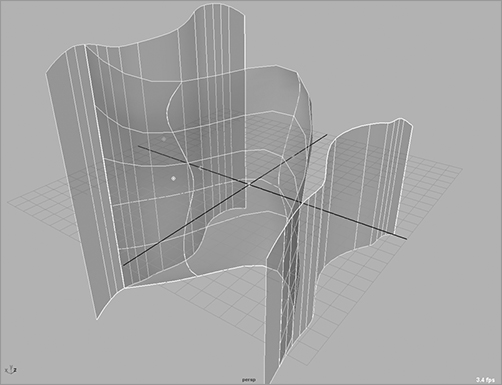
3. Select an isoparm close to the left edge. Press F8 to return to Object Selection mode (or right-click the first curve and choose Object Mode from the marking menu), Shift+click the first curve, and then Shift+click the second curve. Press F8 again or use the marking menu again for Component mode, and Shift+click an isoparm toward the left edge on the second surface, as in Figure 5-14.
Figure 5-13: Two lofted surfaces with two curves in between
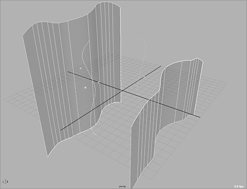
Figure 5-14: Selecting the isoparm

4. Choose Surfaces ⇒ Loft to create the intermediate surface between the existing lofts. Figure 5-15 shows how the new surface snakes from the first loft to the second loft by way of the two curves.
Figure 5-15: The spanning loft between the existing surfaces snakes from the first isoparm to the curves to the second isoparm.
Surface History
In Chapter 3, “The Maya 2011 Interface,” you learned that clicking the History icon (![]() ) toggles History on and off. History has to do with how objects react to change. Leaving History on when creating primitives, as you did in Chapter 2, allows you to access an object’s original parameters.
) toggles History on and off. History has to do with how objects react to change. Leaving History on when creating primitives, as you did in Chapter 2, allows you to access an object’s original parameters.
Leaving History on when creating NURBS surfaces allows the surface to update when any of its creation pieces change. For example, the loft you just created will update whenever the two original surfaces or curves you used to create the loft move or change shape. If you were to move the original loft on the left and rotate it back a bit, the new loft would adjust to keep its one side attached to the same isoparm. If one or more of the input curves were to change, the loft would bend to fit.
You must toggle History on before you create the object(s) if you want History to be on for the object(s).
By lofting using isoparms and with History toggled on, you can keep the new surface permanently attached to the original loft, no matter how the isoparms move, as in Figure 5-16. This technique works with all surface techniques, not just with lofting, as long as History is turned on. History is useful for making adjustments and fine-tuning a surface, and it can be handy in animation if several surfaces need to deform but stay attached.
Figure 5-16: History updates the newly created loft to keep it attached to the isoparms and curves used to create it, even when they’ve been moved or altered.
Why wouldn’t you want History turned on for everything? After a long day of modeling, having History on for every single object can slow down your scene file, adding unnecessary bloat to your workflow. But it isn’t typically a problem on most surface types unless the scene is huge, so you should leave it on while you’re still modeling.
If you no longer want a surface or an object to retain its History, you can selectively delete it from the surface. Select the surface, and choose Edit ⇒ Delete by Type ⇒ History. You can also rid the entire scene of History by choosing Edit ⇒ Delete All by Type ⇒ History. Just don’t get them mixed up!