
Modeling Complex Objects: The Classic Steam Locomotive
This exercise will demonstrate the following polygonal modeling techniques:
- Extrusion
- Insert Edge Loop and Wedge Face tools
- Object duplication
- Pivot placement
- CV curves and revolved surfaces
- Complex model hierarchy
You’ll start to create a rather complex-looking object, an old-fashioned steam locomotive, using mostly polygons. (You’ll create one of the more detailed parts using NURBS patches in the following chapter.) You’ll use a schematic printout of the final model as a reference for your model. Because this is a complicated object, it’s much better to start with good plans. This involves research, web surfing, image gathering, and/or sketching to get a feel for what you’re trying to make.
To begin, create a new project called Locomotive for all the files, or copy the Locomotive project from the CD to your hard drive. If you don’t create a new project, set your current project to the copied Locomotive project on your hard drive. Choose File ⇒ Project ⇒ Set, and select Locomotive.
If you forget to set your project, your rendered images and scene files will be saved into your last project. When you create a new project, Maya automatically sets it as the current project.
Remember that you can enable Incremental Save to make backups at any point in the exercise.
Now, on to modeling a design that’s already sketched and modeled. To begin, study the schematic printout of the final model included in the project’s sourceimages folder. This will help orient you to what you’re building. Typically, you’ll use sketches or downloaded images and such.
Beginning in Chapter 8, “Introduction to Animation,” and following into Chapter 9, “More Animation!” you’ll set up and animate the locomotive. When you’re building any model, it’s important to keep animation in mind, especially as it impacts grouping related objects in the scene hierarchy so that they will move as you intend. Creating a good scene hierarchy will be crucial to a smooth animation workflow; so throughout this exercise, you’ll use the Outliner to keep the locomotive’s components organized as you create them.
The Production Process
The trick with a complex object model is to approach it part by part. Deconstruct the major elements of the original into distinct shapes that you can approach one by one. The locomotive can be broken down into three distinct objects, each with its own subobjects:
- Engine
- Boiler
- Undercarriage
- Cowcatcher
- Cabin
- Wheels
Figure 4-44: A schematic diagram of the finished model

You’ll model each part separately based on the detailed schematic in Figure 4-44.
The Boiler Engine
The most prominent part of a steam locomotive is the steam engine, or boiler. Look at its shape. You can start with a simple cylinder, and work from there. To begin building the boiler, follow these steps:
During this exercise, you’ll switch a few times between the Polygons and the Surfaces menu sets to access the required functions.
1. Create a polygonal cylinder by choosing Create ⇒ Polygon Primitives ⇒ Cylinder. Leave all the creation option settings at their defaults (don’t enable Interactive Creation).
2. Rotate the cylinder 90 degrees in the X-axis to place it on its side. Scale the cylinder to about 1.8 in all axes. Then, lengthen the cylinder until Scale Y is at about 8.9. You can either use the Scale manipulator or enter the values in the Channel or Input Box.
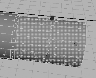
3. You can use the Insert Edge Loop tool mentioned earlier in this chapter to insert edges into the cylinder to make one end smaller. Select the cylinder, and choose Edit Mesh ⇒ Insert Edge Loop Tool ❒. In the option box, make sure Maintain Position is set to Relative Distance From Edge, and Auto Complete is turned on. Your cursor turns into a triangle pointer. In two separate actions, click one of the horizontal subdivisions to create two new vertical edges about one-third of the way in from the right end of the cylinder, as shown in Figure 4-45.
Figure 4-45: The Insert Edge Loop toolcreates subdivisions quickly.

Figure 4-46: Scale the end faces.
4. Right-click the cylinder, and choose Face from the marking menu. Select the end faces, and scale them down a bit as in Figure 4-46. This gives you the main part of the boiler.
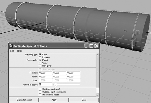
5. Make a new poly cylinder as before. Scale the cylinder to make it a flat plate, and place it on the boiler. The cylinders need to be scaled to fit snugly over the boiler as you see fit. This gives you a simple weld plate to provide the boiler with some detail. Choose Edit ⇒ Duplicate Special ❒ to copy the plate four times in one action. In the option box, set Number Of Copies to 4. Move these duplicates one by one back along the boiler cylinder, and place them through the skinny section of the boiler. Arrange a total of five plates along the boiler, as shown in Figure 4-47.
Figure 4-47: Arrange five plates along the boiler.
Boiler Front Cap
Now you’ll create the boiler’s front cap. You’ll use a NURBS curve to create a NURBS surface using a technique called Revolve, which we’ll discuss in more detail in the next chapter.
Switch to the Surfaces menu, and then follow these steps:
Figure 4-48: Draw a curve to create an outline for the boiler front cover.

1. Choose Create ⇒ CV Curve Tool. In the Side view panel, lay down CVs as shown in Figure 4-48 from the top of the curve down. Make sure you begin the curve about 1.5 units from the Z-axis so you can end the curve on the Z-axis line, as shown in Figure 4-48. When you’ve placed your last CV, press Enter to complete the curve. Don’t worry if it isn’t exactly like the curve shown.
When you finish the curve in step 1, you should notice that Maya no longer displays its CVs in the panel. To display the CVs on a NURBS object, such as this curve, select the object and choose Display ⇒ NURBS ⇒ CVs. You can toggle the CVs off by choosing the same menu items again.
Figure 4-49: Fit the boiler cap onto the boiler engine.

2. This curve is called the profile curve, and it will spin around to sweep a surface for the boiler cap. You need to revolve the curve around its bottom end to sweep a proper surface. Because you created the curve to end on the Z-axis, and the pivot point for the curve is by default at the origin, select the curve and, while still in the Surfaces menu set, choose Surfaces ⇒ Revolve ❒. Set Axis Preset to Z. Click Revolve to create the boiler cap. With the new surface selected, press 3 to display its highest level of detail in the view panels.
Now that you’ve created the boiler cap, select the curve and move it in the scene. Notice that the surface changes. This is how the history is displayed on the resulting surface. As we touched on earlier in the book, Maya’s History functionality keeps a record of how the object was made, as long as the Construction History icon in the Status line is on.
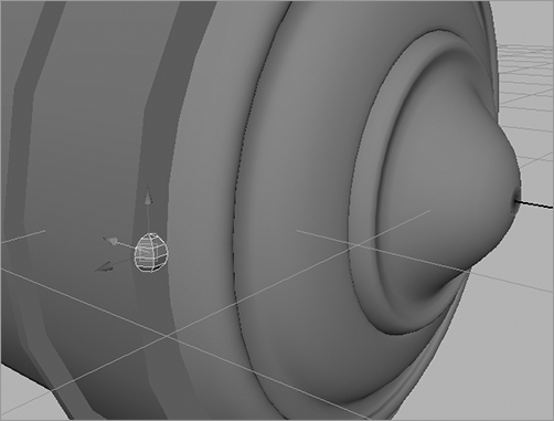
3. You don’t want history on the object, so select the boiler cap and choose Edit ⇒ Delete by Type ⇒ History. Doing so erases the history so the curve no longer affects the surface. Move the boiler cap into place at the front of the boiler. Scale it as needed to fit the cylinder’s skinny end. (See Figure 4-49.)
Adding Details
You’ll include some detail by adding bolts to the front boiler cap and the weld plates. This will introduce you to the process of copying multiple objects into position automatically, otherwise known as copying into an array. To create the bolts, follow these steps:
1. Create a poly sphere by choosing Create ⇒ Polygon Primitives ⇒ Sphere ❒. In the option box, set both Axis Divisions and Height Divisions to 6. Click Create. This makes a crude sphere at the origin, perfect for a bolt. Scale the sphere down to 0.07 in all axes to make it the right size.
2. You need to duplicate this bolt many times to place bolts around the boiler cap and the weld plates. Instead of moving them into position one by one, you’ll create a circular array of bolts that you can group together and slap on the boiler. Move the bolt to the boiler cap, and place it on the left side of the boiler cap, halfway into the surface, as shown in Figure 4-50.
Figure 4-50: Place the bolt on the left side.
3. Enter Pivot Placement mode by pressing Insert (Home on a Mac, or fn + Home on a Mac laptop) to move the pivot of the bolt to the center of the boiler cap, and then exit Pivot Placement mode by pressing Insert (Home) again.
4. You need to copy 19 more bolts to go around the boiler cap at 18-degree intervals, pivoting around the center of the cap. To do so, select the bolt, and choose Edit ⇒ Duplicate Special ❒. In the option box, set Number Of Copies to 19, and set a value of 18 for Rotate Z, as shown in Figure 4-51. Click Apply to copy the bolts all the way around the boiler cap. The copies array themselves around their common pivot point (the center of the boiler plate) at 18-degree intervals.
If you make the copies without moving the pivot point of the original bolt to the center of the boiler cap, none of the 19 copies will be arrayed into a nice circle around the boiler. They will end up in different configurations.
Figure 4-51: Multiple copies of the bolt are placed automatically.

Figure 4-52: Duplicate the boiler bolts for all the plates.

5. Notice that the option box doesn’t close when you click Apply. Make sure to reset Duplicate Special Options back to default. Otherwise, the next time you try to duplicate an object, you’ll get 19 instances of it! In the option box, choose Edit ⇒ Reset Settings.
6. In the Outliner, select the 20 bolts, and choose Edit ⇒ Group (or press the hotkey combination Ctrl+G) to group them. Call the new group boiler_bolts or something similar to keep it organized. Center the pivot on the new group by choosing Modify ⇒ Center Pivot.
7. Select the boiler_bolts group, and duplicate it once to create another set of bolts you can place on the welding plates. You’ll have to scale the duplicated boiler_bolts group up a bit to make all the bolts fit around the weld plates. Repeat for the other plates, as shown in Figure 4-52. Make sure you reset the duplicate options when you’re finished, to keep from making 19 copies next time.
To check your work, or if you’ve skipped ahead to this point, you can load the scene file locomotive_model_v1.mb from the Locomotive project on the CD.
The Undercarriage
Now, you can tackle the base on which the boiler sits. Look at Figure 4-53, which shows a schematic view of the boiler sitting on the undercarriage of the train. Luckily, you have the luxury of referring to the final model here, to visualize what you’re modeling.
Figure 4-53: The schematic view of the boiler and undercarriage

Follow these steps to continue with the engine:
1. Create a poly cube, and scale it to X = 2.7, Y = 2.95, and Z = 17.55. This forms the main length of the undercarriage you saw in the sketch in Figure 4-44, earlier in the chapter. You’ll use extrusions to create the ends. To make viewing easier while you create the undercarriage, you can select all the boiler elements and place them on a display layer to hide them as you work on this section. Alternatively, you can move the cube away from the boiler for the time being and move it back when you’re finished.
2. Switch back to the Polygons menu, and right-click the cube you just created. Choose Face from the marking menu, and select the left end of the face. Choose Edit Mesh ⇒ Extrude. Using the Transform manipulator on the special Extrude manipulator, pull out the face slightly. Use the Scale Y manipulator (the green box) to scale the new face smaller in the Y-axis, and move it up as shown in the left image in Figure 4-54.
3. With the new face still selected, choose the Extrude tool again. Pull a new face out about 2.5 units to create a lip, as shown in the right image in Figure 4-54.
4. At the other end, you need to make a thinner lip. Select the poly object, and choose Edit Mesh ⇒ Insert Edge Loop Tool. Place a horizontal edge about one-fifth of the way down from the top edge. Choose the Extrude tool (from the Edit Mesh menu or from the Polygons tab of the Shelf, using the ![]() icon), and pull out the newly divided face 3.5 units (see Figure 4-55). This completes the main undercarriage piece.
icon), and pull out the newly divided face 3.5 units (see Figure 4-55). This completes the main undercarriage piece.
5. Create three polygon cubes, and scale and position them at the right end of the undercarriage, as shown in Figure 4-56. For now, fit them in without worrying about overlapping or interpenetrating geometry.
Figure 4-54: Extrude the face and scale it down (left), and then extrude that new face again (right).
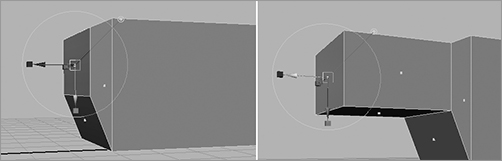
Figure 4-55: Extrude to complete the undercarriage piece.

Figure 4-56: Place three cubes into the undercarriage. The cubes are shown here, highlighted.

If you want to make your models look like the preceding image, with the wireframe lines showing in Shaded mode, enable Shading ⇒ Wireframe On Shaded in the panel view. Doing so helps delineate the model.
6. For a finishing touch, you can round out the lip you created in step 4. Select the face on the end of the lip, and then right-click it again. This time, choose Edge from the marking menu, and Shift+select the bottom edge as shown in Figure 4-57. Choose Edit Mesh ⇒ Wedge Face ❒. Set Arc Angle to 90 and Divisions to 6. Click Wedge Face, and you see a result similar to that shown in Figure 4-58. These little impromptu details help make your model nicer.
Figure 4-57: Select the end face for a Wedge Face operation.
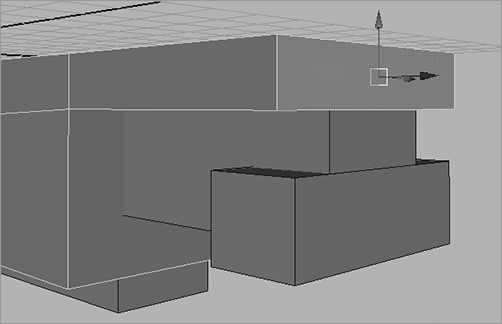
Figure 4-58: The rounded back lip of the undercarriage

7. The next piece of the undercarriage fits on the left or front end and eventually attaches to the locomotive’s cowcatcher. Create a polygon cube, and scale it to X = 4.45, Y = 0.16, and Z = 4.0. Using the Insert Edge Loop tool, place nine equidistant subdivisions on the polygon slab, as shown in Figure 4-59. Notice that if you click and hold with the Insert Edge Loop tool, you can drag the location of the new edge line. This way, you can more easily position the lines.
8. Select the bottom faces, and move them down individually to create an arc, as shown in Figure 4-60. There is no need to extrude the faces; moving them one by one is fine. Place the new piece at the front of the undercarriage, as shown in Figure 4-61.
Figure 4-59: Place nine subdivisions on the poly slab.
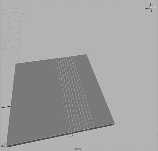
Figure 4-60: Create an arc by moving the bottom faces down individually.

Figure 4-61: Attach the new piece beneath the front of the train.
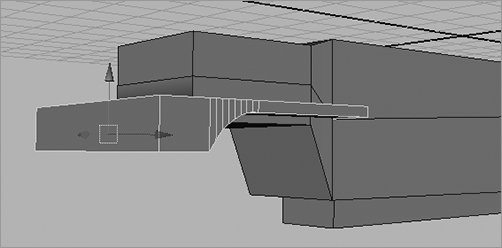
Figure 4-62: Begin the cowcatcher with a simple wedge.

9. Let’s tackle the cowcatcher. Create a polygon cube with eight subdivisions along its width. Scale the cube to 4.4 in X, 2.15 in Y, and 1 in Z. You’ll use this subdivided cube to pull vertices to make a cowcatcher shape. Enter Component Selection mode, pick the front top vertices, and move them down to make a wedge, as shown in Figure 4-62.
10. Select all the front vertices and the middle five back vertices along the bottom. Scale them in together in the Z-axis and then in the X-axis. Move them all forward to create the cowcatcher, as shown in Figure 4-63. Place the cowcatcher at the front of the undercarriage, as shown in Figure 4-64.
11. Place three poly cube slabs approximately as shown in Figure 4-65 for the boiler platforms. Group all these undercarriage pieces together, and name them in a way that will help you stay organized. Also, make sure you group the parts of the boiler in a logical manner. The Outliner is shown in Figure 4-66 with the organization of the model so far.
You can load the scene file locomotive_model_v2.mb from the Locomotive project on the CD to check your work.
Figure 4-63: Scale down the front vertices.
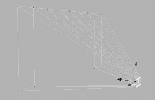
Figure 4-64: The cowcatcher in place

Figure 4-65: The boiler platforms are simple cubes.

Figure 4-66: The Outliner view of the locomotive geometry

Finishing the Boiler
The fun parts of a steam locomotive are all the chimneys on top of the boiler. To create the main steam chimney and give it a revolving surface, follow these steps:
Figure 4-67: The profile curve for the chimney

1. You need to draw a profile curve for the smokestack/chimney. Choose Create ⇒ CV Curve Tool ❒. In the option box, set Curve Degree to 1 Linear. This lets you create straight curves. In the Top view panel, start from the bottom, and lay down CVs similar to those shown in Figure 4-67. Press Enter when you finish. Make sure you reset the options to the defaults when you’re done.
2. This profile curve should be about five units tall in the Z-axis in the Top view panel and have its pivot point at the origin. Enter the Surfaces menu set, select the curve, and choose Surfaces ⇒ Revolve ❒.
Change Axis Preset to Z. Also, at the bottom of the window, change Output Geometry to Polygons. You won’t create a NURBS surface as you did before with the boiler cap but instead will go for a poly revolve. Change Type from Triangles to Quads. This creates polygon faces that are rectangular rather than triangular.
Under Tessellation Method, select Standard Fit. Click Revolve, and you should have a chimney similar to the one shown in Figure 4-68. You may need to orient the chimney to fit the boiler properly if it’s lying flat.
Figure 4-68: The engine’s chimney

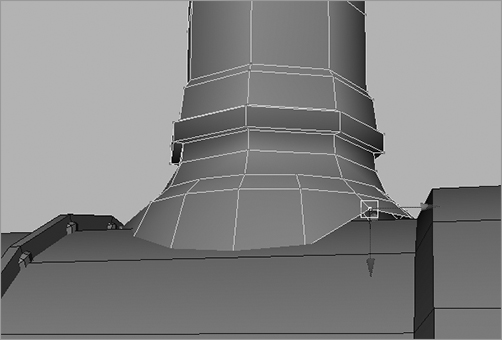
3. Delete the history by selecting the chimney and choosing Edit ⇒ Delete By Type ⇒ History. Place the chimney as shown in Figure 4-68. You can move the vertices at the bottom of the chimney to fit it to the round engine boiler, as shown in Figure 4-69.
Figure 4-69: Edit vertices to fit the boiler around the body of the boiler.
Go Get ’Em, Cowboy (or Cowgirl)!
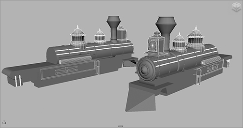
Here is where I kick you out into the cruel hard world and make you create the remaining pieces for the engine boiler before you move on to the steam pumps, main cabin, wheels, and drive axles. You’ll find suggestions on how to create the individual pieces in this section. (You’ll set up the wheels in the animation chapters that follow.)
Study the following figures and graphics to get an idea of how to create these pieces using the Revolve tool and the other polygon toolsets used in this exercise and in this chapter. Figure 4-70 shows the extra pieces for you to build.
Figure 4-70: You’re on your own!
You can build the lantern shown in Figure 4-71 from a polygon cube by adding subdivision edges with the Insert Edge Loop tool and extruding or moving faces in and out. The light itself is a simple cylinder set into this shape.
You can draw the two top boiler caps by drawing a profile curve and then revolving the boiler caps as you did for the chimney (see Figure 4-72).
The piping and small tanks along the length of the engine boiler are cylinders placed in position, as shown in Figure 4-73.
Figure 4-71: Create the lantern from a simple cube.
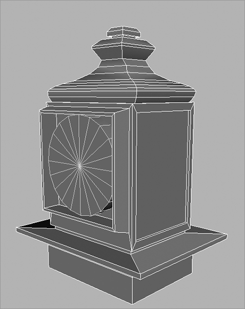
Figure 4-72: Use Surfaces ⇒ Revolve to create the boiler caps.
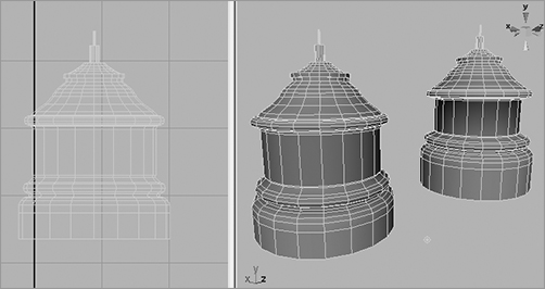
Figure 4-73: Place the piping on the boiler.

Figure 4-74: The side panels
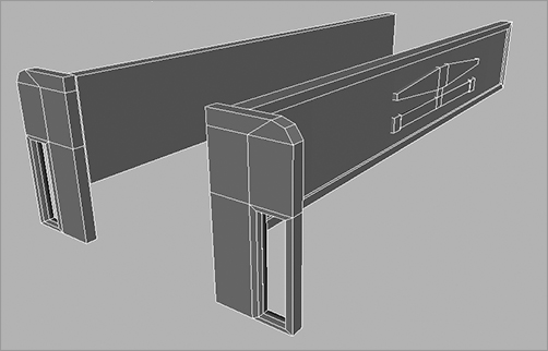
The side panel details are poly cubes that have some faces extruded, with a few faces cut out (see Figure 4-74).
You can load the scene file locomotive_model_v3.mb from the Locomotive project on the CD to go over the models firsthand and get a much closer look. You can use the scene file to help build the pieces shown in this section to complete the engine boiler and its details.
The following sections will cover the cabin and wheels.
The Cabin
All that remains now, as shown in Figure 4-75, are the main cabin, the wheels, and their drive system. You’ll finish those parts in the following sections; you’ll set up, or rig, the wheels for animation in Chapter 9.
Figure 4-75: The remaining parts to make for the locomotive

You’ll start with the main cabin. It has two sections: the cabin itself and the roof. You’ll begin with the roof and work your way down. Follow these steps:
Figure 4-76: Taper the cube by moving the vertices.

1. Make a poly cube, and scale it so that X = 5.6, Y = 1, and Z = 7.7. Select the front vertices (at the right side of the cube in Figure 4-76), and move them back a tad in Z to angle the edge. Do the same to the rear bottom vertices, giving the cube a tapered look in the Z-axis.
2. You need to subdivide the cube. This time, you’ll use the Add Divisions tool. Select the cube, and choose Edit Mesh ⇒ Add Divisions ❒. Make sure Division Levels is set to 1 and Mode is set to Quads. Click Add Divisions. Maya places edges that cut through the middle of the faces.
Figure 4-77: Select and move these edges.

3. Right-click the cube to enter Component Selection mode, and choose Edge from the marking menu. Select the edges as shown in Figure 4-77, and move them toward the back (to the left of the image in the figure) of the roof.
4. Using vertices, shape the roof to match the one in Figure 4-78.
Figure 4-78: Shape the roof to match this shape.

5. Select the bottom two faces, and extrude them down once. Select the back face again, and extrude that down one more time to match the shape shown in Figure 4-79.
Figure 4-79: Continue to shape the roof.

Figure 4-80: The roof is finished.

6. Use the Insert Edge Loop tool to create more subdivisions along the long sides of the roof. Then, move the corner vertices down to angle the side edges of the roof down a little to complete the roof, as shown in Figure 4-80.
7. The cabin is a simple cube that is subdivided with the Insert Edge Loop tool, as shown in Figure 4-81. To make the windows and the open back, select the faces that make up the openings in Component mode, and delete them.
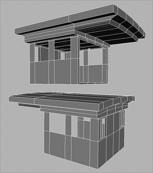
8. Place the roof on top of the cabin, and you’re finished. Figure 4-81 shows the completed main cabin from two sides.
Figure 4-81: The cabin is a cube with some deleted faces.
The Wheels
Figure 4-82: The wheels of the locomotive

What’s a locomotive without wheels? You’ll have two types of wheels: large ones that are driven by the steam pumps and a pair of small wheels in front of the boiler (see Figure 4-82).
To make the large wheels, follow these steps.
1. To create the outer rim of the wheels, create a poly cylinder with Cap Divisions set to 5 in the option box and Axis Divisions set to 20. Scale the cylinder to X = 1.87, and squash it down to Y = 0.145. Turn it up on its side by rotating it 90 degrees in Z.
2. To hollow it out, select the inner faces on the caps, as shown in Figure 4-83, and delete them.
Figure 4-83: Select the inner faces.

3. You should see a wheel rim similar to that in Figure 4-84. It’s hollow on the inside, so you need to close the inside rim. Select the front edges of the inside rim, as shown in Figure 4-84, and choose Edit Mesh ⇒ Extrude. Extrude the edges toward the back side of the rim to close the inside rim.
Figure 4-84: Close the inside rim using Extrude.

Figure 4-85: Create the hub for the wheel’s spokes.

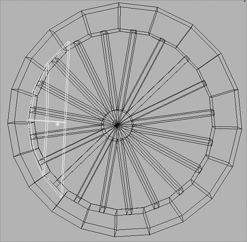
4. The wheel spokes are next. You’ll create the hub of the spokes with a poly cylinder scaled to X and Z = 0.25 and Y = 0.12, so it’s slightly thinner than the rim. Rotate the hub 90 degrees in Z, and place it in the middle of the rim. It helps to snap both the hub and the rim to the same grid point to make sure they’re centered and aligned (see Figure 4-85).
5. Choose the Edit Mesh menu, and make sure the Keep Faces Together option at the top of the menu is unchecked. Select the outer ring of faces on the hub, and extrude them out to meet the rim, as shown in Figure 4-86.
6. Create a poly cube, and shape it as shown in Figure 4-87 to place it against the rim of the wheel on one side. This is where the steam drive’s arm will connect to the wheel.
7. Group the pieces together, and name the node large_wheel. Center the pivot on the hub by choosing Modify ⇒ Center Pivot. If your geometry isn’t perfectly symmetrical, the pivot may not center properly; you’ll have
Figure 4-86: Extrude the outer faces of the hub to create the spokes.
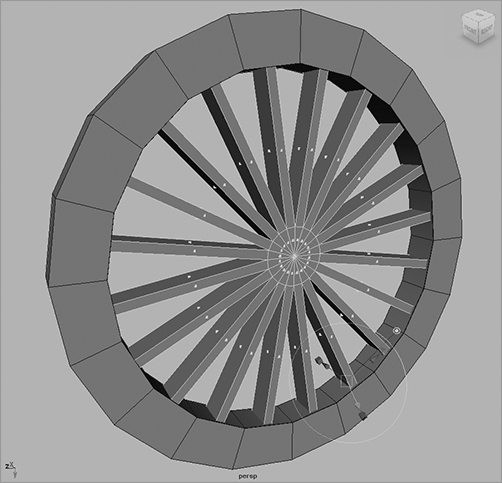
Figure 4-87: Create a plate to which the steam drive’s arm will connect.
to enter Pivot mode (press Insert/Home) and move it manually to the center of the hub. If the top wheel node’s pivot isn’t centered properly, animation will look weird. Duplicate and place the wheels as shown in Figure 4-88. Make sure they all face out properly and align as in the figure.
Figure 4-88: Duplicate and place the wheels.

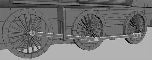
8. The wheel arms are next. These connect the wheels to the steam drive that runs the locomotive. You can use simple poly cubes to make the arms shown in Figure 4-89. Place them as shown, and then rotate the appropriate wheels (using the top large_wheel node) so that they align with the connecting plates. Notice that the arms go through the side panel detail you created earlier with the undercarriage. Group the arms together so you have one group on either side of the train.
Figure 4-89: Add the wheel arms to the wheels to drive the locomotive.
The Small Wheels, the Axle, and the Steam Pumps
They sound like a trio of fifties rockabilly bands, but they’re actually the last parts of the locomotive that you’ll build in this chapter. The small wheels up front are the same as the larger wheels, except they don’t have the connector plate and they have a solid background. You just need to copy one of the large_wheel groups and scale the top node down from 1.0 to 0.575. Delete the connector plate on the side, and place a cylinder behind the wheel to close the back. Remember to group this new closing cylinder into the top node. Call the group small_wheel.
Figure 4-90 shows a small wheel in position.
Figure 4-90: A small wheel in position

The axle that holds the front wheels is easy to make using basic shapes. Using Figures 4-91 and 4-92 as guides, build the axle assembly using simple poly shapes made with primitives and a few subdivision tools and extrusions.
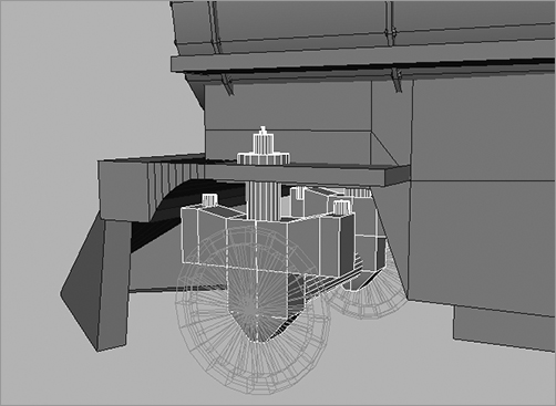
The steam pumps provide drive power to the wheel arms, which in turn rotate the wheels to move the locomotive. These pumps are located on the sides of the engine between the small wheels and the first of the large wheels. They connect down from the boiler and through a drive mechanism to the first set of large wheel on both sides.
Figure 4-91: The front axle

Figure 4-92: The front axle connected to the undercarriage
This drive mechanism rotates the first wheel, which drives the wheel arm to turn the other wheels on the engine. We’ll look at how to set up this relationship in the animation chapters later in the book. For now, let’s make the steam pumps using poly objects, as shown in Figures 4-93 and 4-94.
Figure 4-93: The steam pump is made of two cylinders and an extruded cube.
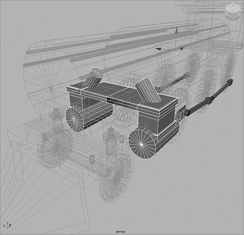
Figure 4-94: The drive mechanism is made of a couple of extruded cubes flanked by poly cylinder rods.

Connect the drive mechanism to the end of the wheel arm. Considering how your model will animate is an important aspect to modeling. This unit will animate in and out of the large pump cylinder, pulling the drive arm back and forth with it.
The completed model is shown in Figure 4-95.
Figure 4-95: You built the whole thing!

Figure 4-96: The Outliner view of the organized scene

Carefully go through your scene and name everything. OK, maybe not everything, but at least name the top nodes and important pieces of the model. Group items neatly so that everything makes sense. In Chapter 8, you’ll learn how best to organize the hierarchy of the model to suit your animation needs.
Figure 4-96 shows the Outliner view of the organization of the final scene on the CD.
Open the scene file locomotive_model_v4.mb from the Locomotive project on the CD to compare with your work and to guide you as you complete your work. Comparing and contrasting are valuable learning aids. Sometimes, figuring out how something was done by starting at the end and working backward (reverse engineering it) will give you a great deal of information.