
Creating Areas of Detail on a Poly Mesh
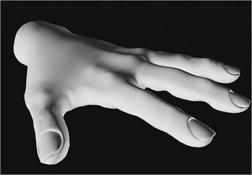
As you saw with the hand, it became necessary to add more faces to parts of the surface to create various details. The hand takes on better form when you devote time to detailing it. We began the hand shown in Figure 4-29 using the previous steps, but we detailed it by creating faces using the tools discussed in this section, moving vertices, and adding fingernails. The most intricate of objects begin from the simplest models. You merely need time and effort to create them. Don’t expect to be able to model intricately right from the start unless you already have modeling experience from another package. Recognizing how to detail models takes a good amount of time and experience; start with simple objects, work your way up, and stay with it.
Maya provides several ways to add surface detail or increase a poly’s subdivisions.
Figure 4-29: This detailed hand can be modeled from a simple cube, given a lot of time and love.
The Add Divisions Tool
You can use the Add Divisions tool to increase the number of faces of a poly surface by evenly dividing either all faces or just those selected. Select the poly surface face or faces, and choose Edit Mesh ⇒ Add Divisions. In the option box, you can adjust the number of times the faces are divided by moving the Division Levels slider. The Mode drop-down menu gives you the choice to subdivide your faces into quads (four-sided faces, as on the left of Figure 4-30) or triangles (three-sided faces, as on the right in Figure 4-30).
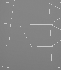
You can also select a poly edge to divide. Running this tool on edges divides the edges into separate edges along the same face. It doesn’t divide the face; rather, you use it to change the shape of the face by moving the divided edges, as shown in Figure 4-31.
Figure 4-30: The Mode drop-down menu of the Add Divisions tool lets you subdivide faces into quads or triangles.

Figure 4-31: Dividing edges

You use the Add Divisions tool to create regions of detail on a poly surface. This is a broader approach than using the Poke Face tool, which adds detail for more pinpoint areas.
The Split Polygon Tool
Figure 4-32: Splitting a Polygon allows you to draw the new edge(s) to split the face.
Another way to create detail is to use the Split Polygon tool, which does exactly what its name suggests. As you’ve seen, when you choose Edit Mesh ⇒ Split Polygon Tool, your cursor changes to a triangle. Use this cursor to select two points along two edges of a face. Doing so creates a straight line from the first to the second point, which serves as a new edge to divide the face into two halves, as shown in Figure 4-32. Notice at lower left in the Help line that a percentage readout gives you the relative position of the tool along the current edge. You can use this readout to help position the new split.
Press Enter to create the new edge and faces, or right-click to continue selecting new points for more edges to split the polygon face. When you’re adding multiple new edges, right-clicking makes for a much faster workflow. Simply pick the first two points, and then right-click. The tool remains active for the next split.
Using the Split Polygon tool is a flexible, accurate, and fast way to create surface subdivisions for your model.
The Insert Edge Loop Tool
Figure 4-33: Using the Insert Edge Loop tool

This handy tool adds edges to a poly selection, much like the Split Polygon tool, but it does so more quickly by working along the entire poly surface, along common vertices. The Insert Edge Loop tool automatically runs a new edge along the poly surface perpendicular to the subdivision line you click, without requiring you to click multiple times as with the Split Polygon tool. You’ll use this tool in the locomotive exercise shortly. You’ll find it indispensable in creating polygonal models because it creates subdivisions quickly.
For instance, subdividing a polygonal cube is quicker than using the Split Polygon tool. With a poly cube selected, choose Edit Mesh ⇒ Insert Edge Loop Tool. Click an edge, and the tool places an edge running perpendicular from that point to the next edge across the surface and across to the next edge, as shown in Figure 4-33. If you click and drag along an edge, you can interactively position the new split edges.
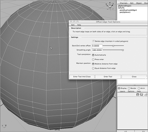
The Offset Edge Loop Tool
Much like the Insert Edge Loop tool, the Offset Edge Loop tool inserts not one, but two edge loop rings of edges across the surface of a poly. Edges are placed on either side of a selected edge, equally spaced on both sides. For example, create a polygon sphere, and select one of the vertical edges, as shown in Figure 4-34. Maya displays two dashed lines on either side of the selected edge. Drag the mouse to place the offset edge loops, and release the mouse button to create the two new edge loops.
The Offset Edge Loop tool is perfect for adding detail symmetrically on a surface quickly.
Figure 4-34: The Offset Edge Loop tool
The Combine and Merge Functions
The Combine function is important in cleaning up your model and creating a unified single mesh out of the many parts that form it. When modeling, you’ll sometimes use several different polygon meshes and surfaces to generate your final shape. Using Combine, you can create a single polygonal object out of the pieces.
The Merge tool is important when you’re creating a polygon model because it fuses multiple vertices at the same point into one vertex on the model. Frequently, when you’re modeling a mesh, you’ll need to fold over pieces and weld parts together. Doing so often leaves you with several vertices occupying the same space. Merging them simplifies the model and makes the mesh much nicer to work with, from rigging to rendering.
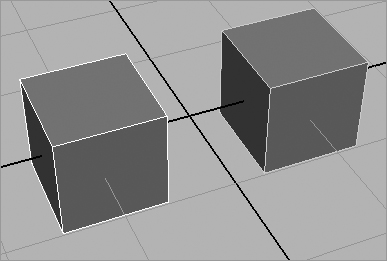
In the following simple example, you’ll create two boxes that connect to each other along a common edge and then combine and merge them into one seamless polygonal mesh. To begin, follow these steps:
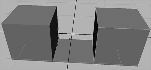
1. In a new scene, create two poly cubes, and place them apart from each other, more or less as shown in Figure 4-35.
Figure 4-35: Place two polygonal cubes close to each other.
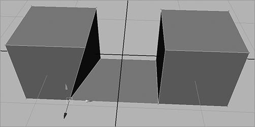
2. Select the bottom edge of the cube on the right that faces the other cube, and choose Edit Mesh ⇒ Extrude. Pull the edge out a little to create a new face, as shown in Figure 4-36. This will be a flange connecting the two cubes. It isn’t important how far you pull the edge out; you’ll connect the two cubes by moving the vertices manually.
Figure 4-36: Extrude the bottom edge to create a flange.

3. Select the first corner vertex on the newly extruded face, and snap it into place on the corner vertex of the other cube, as shown in Figure 4-37. Remember, you can click the Snap to Points icon (![]() ) to snap the vertex onto the cube’s corner.
) to snap the vertex onto the cube’s corner.
4. Snap the other vertex to the opposite corner, so that the cubes are connected with a flange along a common edge, as shown in Figure 4-38.
Figure 4-37: Snap the first corner vertex to the newly extruded face.

Figure 4-38: Snap the other corner vertex.
Even though the cubes seem to be connected at a common edge, they’re still two separate polygonal meshes. You can easily select just one of the vertices and disconnect the connective face of the two cubes. You need to merge the common vertices of the cubes. However, the Merge function won’t work on vertices from two separate meshes. Therefore, you must first combine the cubes into a single poly mesh. The following steps continue this task.
5. Select the two cubes (one has the extra flange on the bottom, of course), and choose Mesh ⇒ Combine. Doing so makes a single poly mesh out of the two cubes. You can now use the Merge function.
6. Even though the cubes are now one mesh, you still have two vertices at each of the connecting corners of the cube on the left. As you can see in Figure 4-39, you can disconnect the flange by selecting a single vertex at the corner and moving it. (Click the vertex to select just one. Don’t use a marquee selection, because that will select both vertices at once.) If you move one of the corner vertices, press the Z key to undo and return the flange to its connected position.
Figure 4-39: There are still two different vertices at the corner, and the boxes aren’t really connected.

7. To merge the vertices at the corners, select both the vertices at the near corner (you can use a marquee selection), and then choose Edit Mesh ⇒ Merge. The two vertices become one. Repeat the procedure for the far corner. Your connected cubes become a single mesh with no redundant vertices. As you can see in Figure 4-40, if you select a vertex at a corner and move it, the cube and the flange both move: there is no disconnect.
If you need to separate a poly mesh back into its component meshes after you combine them, you can select the mesh and choose Mesh ⇒ Separate. But you can’t use Separate if the mesh you’ve combined has merged vertices.
Figure 4-40: The cubes are now connected properly at the corners.
Keeping your meshes simple and organized is important to maintaining a clean and efficient workflow. You’ll notice fewer errors and issues with clean models when you animate, light, and render them. Combining meshes makes them easier to deal with, and Merge cuts down on unwanted vertices and makes working with the mesh cleaner and the surface easier. You’ll find that the more you model with polys, the more useful Merge becomes for creating great models.
If the Merge function isn’t working on vertices in your model, make sure the model is a single mesh; merging vertices with this tool doesn’t work on separate meshes. You must combine them into one poly mesh first.
The Cut Faces Tool
Known as a poly knife in other 3D applications, the Cut Faces tool lets you cut across a poly surface to create a series of edges for subdivisions, pull off a section of the poly, or delete a section. (See Figure 4-41.) Select the poly object, and choose Edit Mesh ⇒ Cut Faces Tool. Click the option box if you want to extract or delete the section.
You can use the Cut Faces tool to create extra surface detail, to slice portions off the surface, or to create a straight edge on the model by trimming off the excess.
Figure 4-41: You can use the Cut Faces tool to create the edges, to pull apart the poly object, or to cut off a whole section.

The Duplicate Face Tool
Select one or more faces, and choose Edit Mesh ⇒ Duplicate Face to create a copy of the selected face(s). You can use the manipulator that appears to move, scale, or rotate your copied face(s).
The Extract Tool
The Extract tool is similar to the Extrude tool, but it doesn’t create the extra faces. Select the face(s), and choose Mesh ⇒ Extract to pull the faces off the surface (see Figure 4-42). If the Separate Extracted Faces option is enabled, the extracted face will be a separate poly object; otherwise, it will remain a part of the original.
Figure 4-42: Pull off the faces.

You can use the Extract tool to create a hole in an object and still keep the original face(s). When you use this tool with the Split Polygon tool to make custom edges, you can create cutouts of almost any shape.
The Smooth Tool
The Smooth tool (choose Mesh ⇒ Smooth) evenly subdivides the poly surface or selected faces, creating several more faces to smooth and round out the original poly object.
The Sculpt Geometry Tool
Figure 4-43: The Sculpt Geometry tool deforms the surface.

You can use a Maya feature called Artisan to sculpt polygonal surfaces. Artisan is a painting system that allows you to paint attributes or influences directly onto an object. With the Sculpt Geometry tool usage of Artisan, you paint on a polygon surface to move the vertices in and out, essentially to mold the surface.
To access the tool in polygon modeling, select your poly object and choose Mesh ⇒ Sculpt Geometry Tool ❒.
For more on sculpting, see the section “Using Artisan to Sculpt NURBS” in Chapter 5. The workflow is much the same as for sculpting with NURBS; the only difference when sculpting polygons is that the surface behaves in a slightly different manner when sculpted. Unlike the NURBS sphere, where the brush strokes give smooth curves in and out, a polygon surface is more jagged. Of course, if you create the poly with a large number of subdivisions, you’ll have a smoother result when using the Sculpt Geometry tool. (See Figure 4-43.)