
References aren’t just for fun! You can also import images into Maya to work directly on the reference. For a model like this, it’s best to create three different image views of the model (front, side, and top) to give you the most information as you build the model. The first step, of course, is to take pictures of your intended model from these three angles. Figures 6-2, 6-3, and 6-4 show photos taken of the front, side, and top views of the wagon.
Figure 6-2: The wagon’s front

Figure 6-3: The wagon’s side view
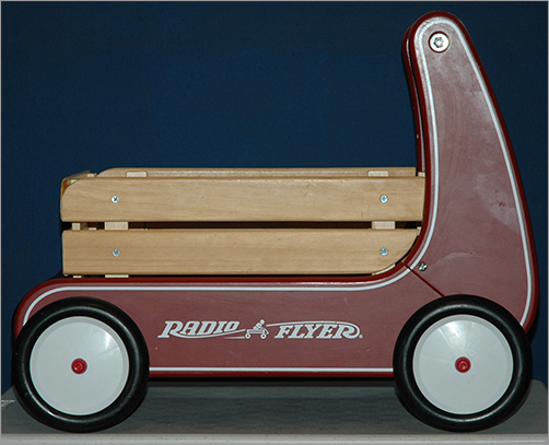
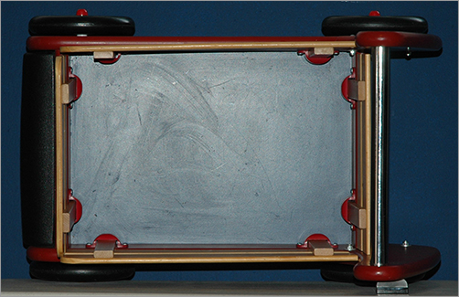
Figure 6-4: The wagon’s top view
The trick here is to bring the photos into an image-editing program, such as Adobe Photoshop, and scale the images to line them up as shown in Figure 6-5. The figure has the added benefit of a view of the wagon taken from the back. The images have been copied and pasted into a larger frame, and grid lines are used to line up the major portions of the wagon, such as its wheels.
Figure 6-5: The views of the wagon roughly lined up in Photoshop

Keep in mind that when you take a photo, in most cases, there will be perspective shift or parallax in the image. Because of that shift, the different views of the same object will never exactly line up. As you can see in Figure 6-5, the height of the wagon doesn’t line up between the front view and the back view, even though all the other major elements of the wagon are in alignment. This is due to perspective shift. Because the handle of the wagon is farther back from the lens of the camera in the front view, it appears lower in the frame than the handle in the back view.
Complete accuracy isn’t what you’re after in this situation. You just want to have a reasonable reference, and this will be more than adequate. Now, you’ll import the images and create the model reference planes on which to work.
Creating Reference Planes for the Images
The reference views of the wagon have already been created for you. You can find them in the Sourceimages folder of the RedWagon project. They’re shown in Table 6-1. Hoorah!
Reference Views and Sizes
Why is the image resolution important? Well, it’s not so much the resolution of the photos, but rather the aspect ratio of each image. To properly map these images onto the planes you’ll use in Maya, each plane has to be the same ratio in scale as its image. For example, an image that is 100 × 50 pixels has an aspect ratio of 2:1 and is, therefore, a wide horizontal rectangle. For it to map properly, the plane on which it’s mapped in Maya must also have a scale ratio of 2:1, so that it’s also a wide horizontal rectangle. Otherwise, the image may distort. The more accurate your model needs to be, the more accurate your photos and their planes need to be.
You’ll need to create three planes for each of the three views. First, make sure Interactive Creation is turned off, and then follow these steps:
Figure 6-6: Creating a plane for the top view
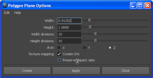
1. In the Front view panel, create a polygonal plane by choosing Create ⇒ Polygon Primitives ⇒ Plane ❒. This plane is for the front image, so in the Options box set Axis to Z, Width to 0.912, and Height to 1.0. Make sure the check box for Preserve Aspect Ratio is deselected, as shown in Figure 6-6. Setting Axis to Z will place the plane properly in the front view.
2. Switch to the Side view panel. Create a second plane, this time with Width of 1.235 and Height of 1. Set Axis to X, and make sure the Preserve Aspect Ratio check box is unchecked.
Figure 6-7: The three view planes are ready.

3. Switch to the Top view panel. Create a third plane with Width of 1.49, Height of 1, and Axis set to Y. Make sure the Preserve Aspect Ratio box is still unchecked. Your Perspective panel should look like Figure 6-7.
Now that all three image planes have been created with the proper aspect ratios, you’re ready to map the photos to them to create the reference for the model.
Mapping the Reference Planes
To map the photos of the wagon to the reference planes, follow these steps:
1. Open the Hypershade (Window ⇒ Rendering Editors ⇒ Hypershade). Open a file browser, and navigate to the Sourceimages folder of the RedWagon project on your hard drive.
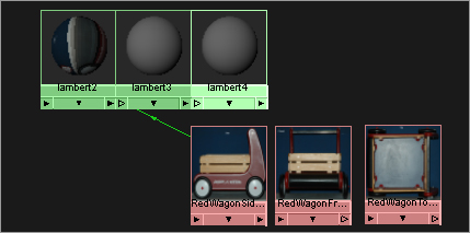
2. Click the first image in your file browser, and drag it into the work area of the Hypershade window to import the file image. Drag the other two images into the Hypershade, as shown in Figure 6-8.
Figure 6-8: Importing the photos into the Hypershade window

3. Before you can assign the images to their respective planes, you must create shaders for each of the planes. In the left panel of the Hypershade window, click the Lambert icon three times to create three new Lambert shaders, as shown in Figure 6-9. For more information about shaders and texturing, see Chapter 7.
4. While still in the Hypershade work area and while holding down the Ctrl key, MMB+drag the side-view photo swatch onto the first Lambert shader icon. Maya automatically maps the image to the color of the Lambert shader, as shown in Figure 6-10. You can also MMB+drag the image to the Lambert Shader icon and then choose Color from the context menu that appears.
Figure 6-9: Create three new Lambert shaders.

Figure 6-10: Connecting the image to the shader’s color
5. Ctrl+MMB+drag the other two images onto their respective Lambert shaders to connect them.
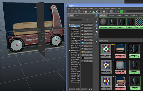
6. Assign the shaders to the reference planes. To do so, MMB+drag the Lambert shader that is connected to the side-view image to the side-view plane in the Perspective panel. Switch the perspective view into Texture mode by pressing 6 while in that panel. You should see the image of the wagon appear, as shown in Figure 6-11.
Figure 6-11: The side-view photo is mapped to the side-view plane.
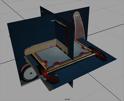
7. Drag the top-view Lambert shader to the top reference plane and the front Lambert shader to the front reference plane to assign the other two views. You should now have the three reference planes laid out as shown in Figure 6-12.
Figure 6-12: All three reference planes are mapped.
8. All isn’t rosy yet! The front reference view and the side reference view seem to match up, but the top reference view is off. Select the top reference plane, and rotate it 90 degrees in the Y-axis. Although it’s oriented properly now, the top view is larger than the side-view plane, and the images still don’t line up.
9. Scale the top reference plane to match the width of the side-view plane, as shown in Figure 6-13.
10. Remember that the scale of these planes is small right now. You don’t need to use real-world units for this project. However, you should scale the reference planes so that you have a larger scale with which to work. Select all three reference planes, and scale them to about four times their previous size. Don’t enter values in the Channel Box; you should scale them by sight. Remember to scale all three reference planes together.
11. To give yourself more room to work, select the front-view plane and move it back, as shown in Figure 6-14.
12. Create a display layer for the planes to make it easy to manage them later. To do so, in the Layer Editor below the Channel Box, click the Create a New Layer icon (![]() ). Double-click the new layer, and name it referencePlanes in the window that pops up (see Figure 6-15). Click Save. Your Layer Editor should resemble the one shown in Figure 6-16.
). Double-click the new layer, and name it referencePlanes in the window that pops up (see Figure 6-15). Click Save. Your Layer Editor should resemble the one shown in Figure 6-16.
Figure 6-13: Scale the top reference plane to match the side reference plane.
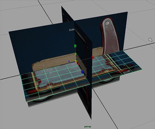
Figure 6-14: Scale up the planes together, and then move the front reference plane back.

Figure 6-15: Name the new layer.

Figure 6-16: The new layer in the Layer Editor
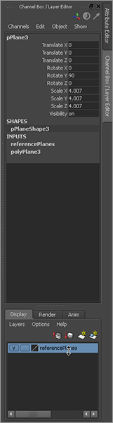
13. Select all three reference planes, RMB+click the referencePlanes layer, and choose Add Selected Objects from the context menu. For more on the Layer Editor, see “The Channel Box/Layer Editor” section in Chapter 3, “The Maya 2011 Interface.” To toggle the display of the reference planes to get them out of the way, simply toggle the box to the extreme left of the layer name. It’s currently checked with a V for Visible in Figure 6-16.
Save your work, and “version up” so you don’t write over your previous scene files. You can load the scene file RedWagonModel_v01.ma from the Scenes folder of the RedWagon project on the CD to check your work or skip to this point. Just make sure to set your project to the RedWagon project on your hard drive after copying the entire project from the CD.
To remain in step with this chapter, make sure Interactive Creation is turned off when you create a new primitive.