
Cameras capture all the animation fun in the scene. In theory, Maya’s cameras work the same way as real cameras. The more you know about photography, the easier these concepts are to understand.
The term camera, in essence, refers to the perspective view. You can have as many cameras in the scene as you want, but it’s wise to have a camera you’re planning to render with placed to frame the shot and another camera acting as the perspective work view so you can move around your scene as you work. The original persp panel fits that latter role well, although it can be used as a render camera just as easily.
You can also render any of your work windows to test render orthogonal views of your model the same way you render a perspective view.
Creating a Camera
The simplest way to create a new camera is to choose Panels ⇒ Perspective ⇒ New, as you’ve seen in a previous exercise. This creates a new camera node in Maya and sets that active panel to its view.
You can select a camera and transform it (move it, rotate it, scale it) just as you would select and transform any other object in Maya to be animated or positioned. Furthermore, you can move a camera and rotate it using the Alt/Option key and mouse button combinations.
For example, click inside a new Maya Scene Perspective window to make it active. Select that view’s camera by choosing View ⇒ Select Camera. The camera’s attributes appear in the Channel Box. Try moving the view around using the Alt/Option key and mouse button combinations. Notice how the attributes change to reflect the new position and rotation of the camera. You can animate the camera—for example, zoom in or out or pan across the scene—by setting keyframes on any of these attributes.
Camera Types
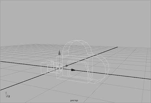
Figure 11-14: A single-node camera
You can create three types of nonstereo cameras for your scene: Camera; Camera and Aim; and Camera, Aim, and Up (also known as single-node, two-node, and three-node cameras, respectively). To create any of these cameras, choose Create ⇒ Cameras. You can also change the type of these cameras at any time through the Attribute Editor. The other two options for creating cameras are Stereo Camera and Multi Stereo Rig to allow for a stereoscopic effect, although they aren’t covered in this book.
The single-node camera (Camera) is the most common (see Figure 11-14). This camera consists of a single camera node that you move and rotate as you would any other object for proper positioning. The persp panel’s camera is a single-node camera.
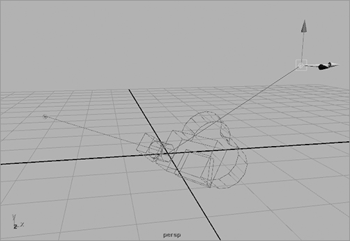
The two-node camera (Camera and Aim) consists of the camera node and an aim node. You use the aim node to point the camera as opposed to rotating it to orient it properly. This is useful for animating a camera following an object. You animate the movement of the aim node to follow your object much as a car around a racetrack. The camera pivots to follow its aim point and, hence, the object. (See Figure 11-15.)
The three-node camera (Camera, Aim, and Up) has a camera node, an aim node, and an up node. The additional up node is to orient the camera’s up direction. This gives you the ability to animate the side-to-side rotation of the camera as well as its aim direction. (See Figure 11-16.)
Figure 11-15: A two-node camera

Figure 11-16: A three-node camera
Camera Attributes
As an example, set your project to Lighting, and load the still_life_render_v02.mb scene from the Lighting project on the CD. You’ll see a green box in the persp panel that displays the resolution (set to 640 × 480) and the name of the camera (camera1).
Figure 11-17: The Attribute Editor for the camera

Special attributes control the function of camera nodes. To set these attributes, follow these steps:
1. With camera1 selected, open the Attribute Editor (press Ctrl+A or choose View ⇒ Camera Attribute Editor).
2. At the top of the window, select the type of camera controls you want. The Controls attribute sets the type of camera from single- to two- to three-control nodes. Figure 11-17 shows the Attribute Editor for the camera.
Focal Length
The Focal Length attribute specifies the length of the lens. The lower the focal length (a.k.a. short lens), the wider the view. At very low numbers, however, the image is distorted, as you can see in the comparison in Figure 11-18. The higher the focal length, the closer the subject seems to the camera.
Figure 11-18: Different focal lengths
Although adjusting the Focal Length attribute of a camera zooms in and out, it isn’t the same as moving the camera closer to your subject using the Alt+right-click procedure to zoom in view panels. Focal-length zooming can create optical distortions, such as can be created with a fish-eye lens.
When you want to animate your camera getting closer to the subject of your shot, it’s best to animate the camera and not the focal length. However, if you need to match some CG element in Maya to a photograph or video you’ve imported as an image plane, set your camera’s focal length to match that of the real camera used for the background.
Clipping Planes
All cameras in Maya have clipping planes that restrict the amount of information that can be seen through them. The clipping plane is defined by the Near Clip Plane and Far Clip Plane attributes. These set the minimum and maximum distance, respectively, of the clipping plane. Any object or portion of an object that passes beyond these distances won’t show in the window and should not render.
If you notice objects disappearing as you move your camera and create a scene, it may be because of the clipping plane. Increase the Far Clip Plane attribute, and the objects should reappear in the view.
Film Back
The Film Back attributes concern the type of output you’ll be dealing with after your renders are finished and you’re ready to put your animation on tape, DVD, film, or what have you:
Film Gate Defines the aspect ratio of your camera’s view. Most images that are output to television have an aspect ratio of 1:1.33, exemplified by the 35mm TV Projection selection in the Film Gate drop-down list box, which is preferred for broadcast video. (For more on aspect ratios, see Chapter 1.)
Fit Resolution Gate Allows you to align footage you may have imported as an image plane to match up CG properly to live action.
Overscan
Found under the Display Options section for the camera’s Attribute Editor, Overscan lets you resize the view without changing the film gate that will render. For example, the scene on the left in Figure 11-19 is set up with an Overscan setting of 1.3, allowing you to see more than what will render, which is defined by the outline box. The scene on the right in Figure 11-19 is set up with an Overscan setting of 2, which increases even more how much you see in the camera1 panel but doesn’t change the view when rendered.
Figure 11-19: Overscan settings define how much you can see of your scene in the camera, but not how much renders in the image.
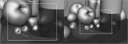
Figure 11-20: Camera display options

You can turn the green box in the panel on and off through the camera’s Attribute Editor. Also in the Display Options section are Display Film Gate and Display Resolution check boxes, shown in Figure 11-20. Ideally, these two green boxes should align perfectly in the view pane. If the resolution box (the solid green line) doesn’t line up with the film gate box (the dashed green line), change your film gate selection to match the resolution’s aspect ratio in the Render Settings window. A resolution of 640 × 480, for example, has an aspect ratio of 1.33, the same as the 35mm TV Projection film gate currently selected for this scene.
Environment
In the Environment section, you’ll find attributes to adjust the background color that renders and to create an image plane as shown in Figure 11-21.
Figure 11-21: Adjusting the camera’s environment and creating camera image planes

If you want to use a solid color as the camera’s background when you render, click the color swatch next to Background Color to change the background color in your renders using the Color Chooser. The slider allows you to control the value, or brightness, of the current color. Neither changes the background color of your view panels, however.
Camera Image Planes
Figure 11-22: An image to import as a camera image plane

A camera image plane isn’t like the reference planes you used for modeling the red wagon in Chapter 6. In this case, an image plane is created to be a background specific for that particular camera or view panel, but it’s typically also used as a reference much like the planes you created and mapped in Chapter 6. Camera image planes are useful when you’re matching your scene to existing footage or an image. For example, if you need to animate a flying saucer to a home video of a family gathering, you would import the video as an image sequence into Maya through a perspective camera to be able to line up your UFO properly to zap your cousins.
You can import an image plane by clicking the Create button in the Environment section of the Attribute Editor (see Figure 11-21) or directly through a view panel’s menu, as you’ll see in the next exercise.
In this exercise, we’ll show you how to import a sketch of an axe into the Front view panel for a modeling assignment. (You won’t actually model the axe, however.) The image, a sketch of a simple axe design, is to be used as a template for outlining the model. You can find the file Axe_outline_1.tif in the Sourceimages folder of the Axe project on the CD; it’s shown in Figure 11-22. Follow these steps:
1. Choose File ⇒ New Scene.
2. Import the sketch of the axe into Maya as a camera image plane for the Front view panel. In your Front window, choose View ⇒ Image Plane ⇒ Import Image.
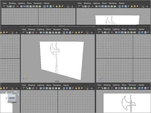
3. Point to Axe_outline_1.tif in the Axe project’s Sourceimages folder, and load it. The sketch displays full screen in your Front window and as a plane in the Perspective window (see Figure 11-23).
Figure 11-23: Importing a camera image plane into the Front view panel
Now you’d be ready to trace the outline of the axe easily in the Front view panel, if you were going to model the axe.
If you can’t see the image plane, click Show in the view panel, and make sure Cameras is checked.
Image Plane Sequence
Figure 11-24: Importing a sequence of image files as a camera image plane

A movie file or a sequence of files can also be brought in to animate or to track motion (a.k.a. matchmoving) as a camera image plane. It’s generally best to use a frame sequence, however. When you bring in an image for an image plane, check the Use Image Sequence box in the image plane’s Attribute Editor window, as shown in Figure 11-24. Maya will automatically load the image to correspond to the frame number in the scene. For example, at frame 29 in your Maya animation, Maya loads frame 29 of your image sequence. But your image file sequence must be numbered correctly (such as filename.###.jpg). You can import an image plane into any perspective view in exactly the same way.
If the clutter of seeing a camera image plane in the other windows bothers you, under the Image Plane Attributes in the Attribute Editor, change the radio button selection next to Display from In All Views to Looking Through Camera. This setting removes the image plane from the other windows.