
In this section, you’ll set up the Decorative Box scene with lights so that you can render them in the next chapter using displacement maps, HDRI, mental ray, and Final Gather to match the lighting in a photo of the real box. Because most of your “lighting” look results from using an HDR image, the lighting you’ll start with will be basic for now.
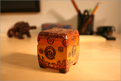
The lighting conditions you’ll use as a starting point are shown in Figure 10-58 as well as in the Color Section of this book. You can see that there is a primary key light coming from the right side of the image, slightly from the front, with a good fill from the left side and from top back, which also gives a bit of a rim light. These lights will be easy to set up to get the general feel first. The finesse of this exercise will come from rendering through mental ray in the next chapter, using an HDR IBL, adding reflections to the box, adding displacement maps for the intricate carvings, and adjusting the shaders to taste. In the following exercise, you’ll create a basic lighting setup for the decorative box and get a direct lighting solution first.
Figure 10-58: Lighting the decorative box using this practical lighting as reference.
Set your current project to the Decorative_Box project, which you should have already copied to your hard drive from the CD. To begin lighting, open the boxLighting01.mb scene file from the Scenes folder of the project. Then, follow these steps:
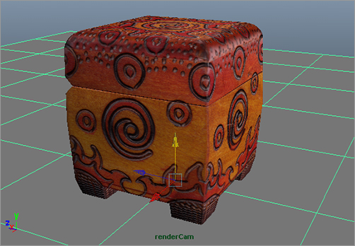
1. Create a new camera that you can use to render the scene. You’ll keep using the persp camera to navigate through the scene. In one of the other view panels, click Panels ⇒ Perspective ⇒ New. Persp1 is created. Then, choose View ⇒ Camera Attribute Editor. Maya shows you the persp1Shape tab.
In the Output Settings heading, make sure the Renderable box is checked. Click the persp1 tab in the Attribute Editor, and rename the camera from persp1 to renderCam (persp1Shape is automatically renamed to renderCamShape).
Select the original persp camera, and, in the Attribute Editor, make sure the Renderable box is unchecked. This ensures that only the correct camera (renderCam) will render.
2. Select the renderCam again, and set its Focal Length attribute to 50. This places a 50mm lens on the renderCam to better match the camera taking the photo in Figure 10-58. Setup the renderCam to approximate the same angle of view in that photo.
Figure 10-59: Lock the camera in place.
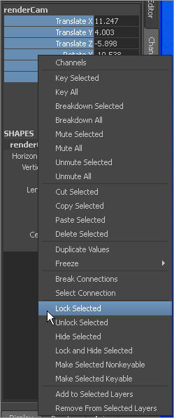
3. Press Ctrl+A to toggle off the Attribute Editor and show the Channel Box. In the Channel Box, select the renderCam’s Translate and Rotate attributes, right-click, and select Lock Selected from the context menu shown in Figure 10-59. Doing so locks the camera in place, disallowing you from moving it. This way, you won’t accidentally mess up the view. To be able to move that camera again, highlight those attributes, right-click them, and select Unlock Selected from the context menu.
4. In the renderCam panel, press 6 for textured display and then 7 for lighted and textured display. This way, you can more easily see how you orient the lights.
5. Using the persp view, create a Directional light for the key light, and place it on the right side of the box, slightly in front, and angled down at about 45 degrees as shown in Figure 10-60. Set the Intensity to 1.5, and turn on Use Ray Trace Shadows under the Shadows ⇒ Raytrace Shadow Attributes heading.
Figure 10-60: Create the key light, and place it as shown.

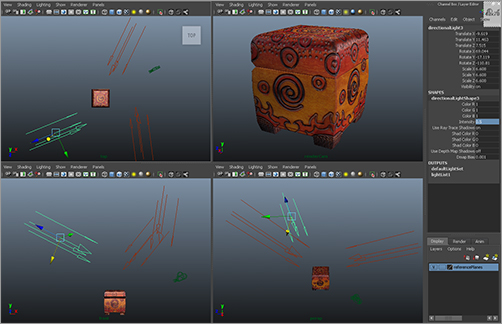
6. Create another Directional light, and place it as the fill light from the opposite angle from the left side and a bit higher and angled down more than the key light, as shown in Figure 10-61. Set Intensity to 0.35, and turn on Use Ray Trace Shadows. Isn’t this exciting?
7. Create a third Directional light. Place it behind the box on its left side, almost diametrically across from the camera, and a bit higher than the box, as shown in Figure 10-62, so you get a nice light grazing across the top of the box. Set Intensity to 0.5.
Figure 10-61: Create the fill light.
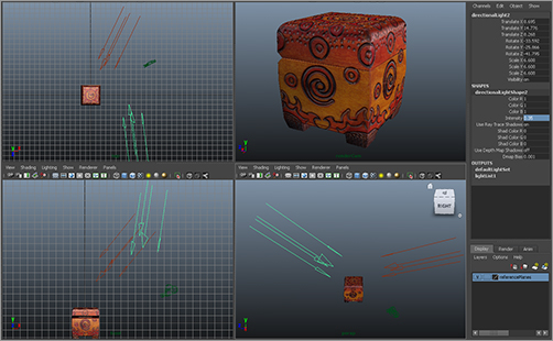
Figure 10-62: Create the back light.
8. Create a poly plane, and scale it up to 50 in X and Z. Place it under the box to make a floor. Its default gray Lambert shader is fine for now. (See Figure 10-63.)
Figure 10-63: Create a floor plane.
9. Open the Render Settings window, and select mental ray as the renderer. This also automatically turns on raytracing, which you need for the shadows from the key and fill lights. Render a frame in the renderCam view.
Figure 10-64 shows the first render with these three lights. Notice that the gray floor is reflecting in the box because you have a Phong shader assigned to it. You can use texture maps to adjust the reflective areas of the box and dial in the proper reflections in the next chapter as you render.
10. Select the key light (directionalLight1), and open the Attribute Editor. In the Raytrace Shadow Attributes heading, set a Light Angle of 3.5 and Shadows Rays of 64. Render. The primary shadowing on the floor looks much nicer.
Select the fill light (directionalLight2), and set its Light Angle to 7 with Shadow Rays of 72 (see Figure 10-65). Play with the radii and number of rays to get the shadows to your liking. Notice how much longer the render takes with soft shadows enabled. You can temporarily use fewer Shadow Rays on your lights until you’re ready for final renders, to save yourself some time. Just don’t forget to turn those attributes back up to their full-quality looks!
Figure 10-64: The render doesn’t look too bad with just the three-point lighting.

Figure 10-65: Much nicer shadows on the floor

11. You may be bothered by the low-quality settings on the render and the slight fuzziness of the wood texture on the box. Open the Hypershade, and click the Textures tab in the top part of the window to show the texture nodes in the scene. Select the box’s color texture node (file1), and open the Attribute Editor. At the top, change Filter Type from the default Quadratic to Off. This prevents the renderer from slightly blurring the texture image to smooth it. (See Figure 10-66.)
12. Open the Render Settings window (![]() ), and click the Quality tab. Set Max Sample Level from 0 to 1. (See Figure 10-67.)
), and click the Quality tab. Set Max Sample Level from 0 to 1. (See Figure 10-67.)
Figure 10-66: Turn off filtering for the color texture image.

Figure 10-67: Select a slightly better render quality in the Render Settings window.
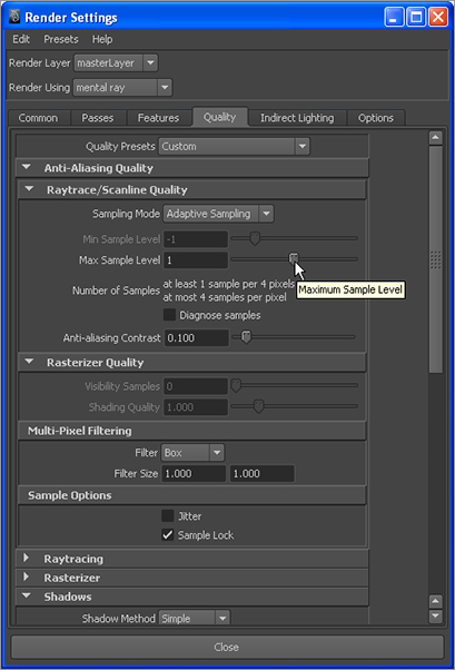
Figure 10-68: The render is much crisper and a bit cleaner.
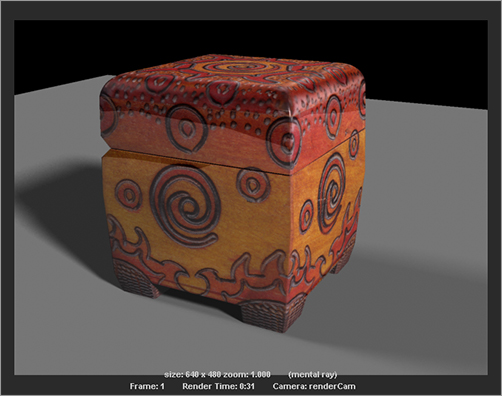
13. Save your previous render in the buffer by clicking the Keep Image icon (![]() ) in the Render View window. A scroll bar appears at the bottom of the Render View window. Render a frame of the persp panel now that you’ve turned off filtering for the texture file and increased a quality setting. Use the scroll bar in the Render View to scrub back and forth between the older fuzzy render and the new unfiltered render. The box’s decorative carvings and lines appear much stronger and crisper, as shown in Figure 10-68. It may be tough to compare the quality levels of the two renders in the book’s black-and-white images, but you should notice them clearly in your Render View.
) in the Render View window. A scroll bar appears at the bottom of the Render View window. Render a frame of the persp panel now that you’ve turned off filtering for the texture file and increased a quality setting. Use the scroll bar in the Render View to scrub back and forth between the older fuzzy render and the new unfiltered render. The box’s decorative carvings and lines appear much stronger and crisper, as shown in Figure 10-68. It may be tough to compare the quality levels of the two renders in the book’s black-and-white images, but you should notice them clearly in your Render View.
You’ll pick this exercise up from this point in Chapter 11, where you’ll add more texture maps to control reflections as well as add carving detail and enable Final Gather to use an HDR image to light the scene. Woo!
The scene file boxLighting_v02.mb in the Scenes folder of the Decorative_Box project gives you this lighting setup.