
This next project will exercise your use of hierarchies and introduce you to creating and refining motion to achieve proper animation for a more complex scene than the bouncing ball. The workflow is simple but standard for properly setting up a scene for animation, also known as rigging, especially for more complex objects, as you’ll see later in this and the next chapter when you rig the locomotive for animation. First, you’ll model an axe and a target, and then you’ll set up the grouping and pivots for how you want to animate. Then, you’ll throw your axe!
Why won’t you throw the NURBS axe you’ve already created and textured? Because later in this chapter, you’ll need it for an exercise on importing and replacing an object in Maya while keeping the animation intact.
The Preproduction Process
To begin the animation right away, you’ll create a basic axe, focusing on the animation and the technique. Toward this end, connect to the Internet if you can, and look up axes and the art of axe throwing to get more familiar with the task at hand. You’ll also need to create a simple bull’s-eye target at which to throw your axe, so look for some references for a target as well.
Create a new project; choose File ⇒ Project ⇒ New. Place this project in the same folder or drive as your other projects, and call it Axe. Click the Use Defaults button to fill in the rest, and click Accept. Click the Animation Preferences button, and set the frames per second to 30fps. Later, you’ll replace this simple axe with a finer NURBS axe model to learn how to replace objects and transfer animation properly in Maya.
Setting Up the Scene
To get started, model the axe and target from primitives, and set up their grouping and pivots. When your scene is set up properly, you’ll animate. It’s important to a healthy workflow that you make sure the scene is set up well before you begin animating.
Making the Axe
The axe will be made of two polygon primitives: a cylinder and a cube. Follow these steps:
1. Choose Create ⇒ Polygon Primitives ⇒ Cube ❒. Set Width Divisions to 4, and click Create.
2. Call this cube axe_head.
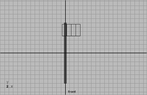
Figure 8-14: Placing the axe’s head on the handle
3. Choose Create ⇒ Polygon Primitives ⇒ Cylinder to create a cylinder to be the handle for your axe, and call it handle.
4. Scale the cylinder so that it’s about one-half unit across and about 14 units tall.
5. Move the cube to the top of the cylinder, leaving just a little of the tip showing, and scale it so that it’s about 2.5 units high and 4 units wide in the front view. (See Figure 8-14.)
6. Scale the cube in the Z-axis so that it’s just a little thicker than the handle.
7. To put a sharp edge on the axe, go into Component mode (F8), and select the four vertices on the very end of the cube:
- Press R to activate the Scale tool.
- Scale the vertices down in the Z-axis to a sharp edge, and scale them slightly up in the Y-axis.
- Select the next four vertices in from the edge. Scale them down in the X-axis about halfway, and scale them up slightly in the Y-axis. (See Figure 8-15.)
8. Press F8 to get back into Object mode, and select both pieces.
Figure 8-15: Creating a sharp edge for the axe
Most animation work doesn’t depend on precise measurements. The key is using proportions and relative sizes. You can almost always use Maya’s generic units (which are set to centimeters by default). The scope of your project will determine if greater precision is necessary.
9. Choose Edit ⇒ Group to group the pieces into one hierarchy, and call it axe.
Now, you need to identify the center of balance for this axe. Doing so will give you the place for your pivot point. Because the heaviest part of this axe is the head, the center of balance is toward the top of the handle. In addition, the axe head protrudes in only one direction, so the balance point is a unit or two away from the handle.
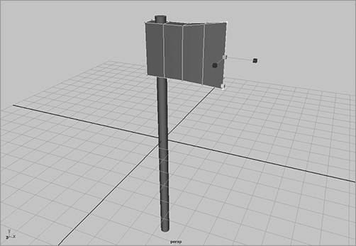
10. Press Insert to activate the Pivot manipulator, and move the pivot just under the axe head and about 1 unit from the handle, as in Figure 8-16.
Your scene should now look like the file axe_v1.mb in the Scenes folder of the Axe project on the CD.
Figure 8-16: Find the axe’s center of balance to determine the proper place for its pivot point.
Making the Target
Move the axe about 40 units in the negative X-axis away from the origin to make some room for the throw, and move it about 15 units up in the Y-axis. Now, you need to create a simple target for your axe to hit. Follow these steps:
1. Start with a polygonal cylinder.
2. Scale down the cylinder’s height to make it squat, and rotate it just a bit past being perpendicular to the ground, facing somewhat toward the sky.
3. Scale the cylinder up about seven times its original size.
You also need to create a simple stand upon which to rest the target. Follow these steps:
1. Choose Create ⇒ Polygon Primitives ⇒ Cube for the base.
2. Scale the cube so that the target fits on the base with some room to spare.
3. Choose Create ⇒ Polygon Primitives ⇒ Cylinder to create two cylinders, to make a cross brace for the back of the target.
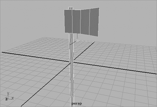
4. Scale, rotate, and position the cylinders to fit behind the target and into the back of the base. Figure 8-17 shows the positions of the pieces to make up the target.
Figure 8-17: Positioning the cross braces for the target
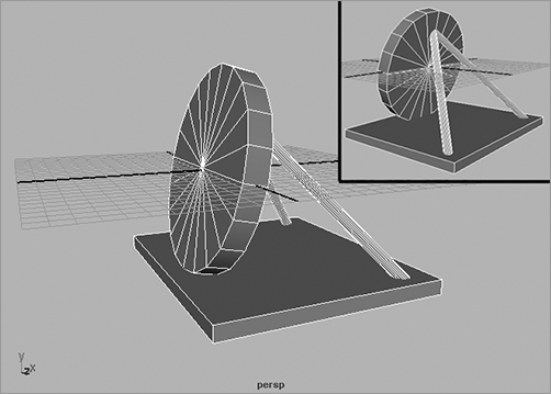
Figure 8-18: The proper placement of the target’s pivot point

5. When you’re happy with the target, group the four objects together and name the group Target.
6. Move the target about 40 units in the positive X-axis away from the origin, and move it up in the Y-axis so its base is basically on the ground plane.
7. Press Insert to move the target’s pivot point to the bottom of the base, right where the cross beams connect to it. Figure 8-18 shows the proper pivot placement.
You place the pivot point at that location because the target will jerk up and back a little bit when the axe hits it. This is the best point for you to rotate around to lift the front of the base up a little to make it look like the axe is really hitting it. Save your file as your next version number. The scene is now ready for animation.
Preproduction: Keyframes and Motion Study
What separates good animation from bad animation is the feeling of weight that the audience infers from the animation. Being lifelong observers of natural physics, people instinctively understand how nature works in motion. You see an object in motion, how it moves, and how it affects its surroundings. From that, you can feel the essence of its motion, with its weight making a distinct, albeit subliminal, impression on you. As it pertains to animation, that essence is simply called weight, and its observation is called motion study.
Unfortunately, merely knowing how something should look while moving isn’t all you need to animate it properly. Giving the axe believable weight is your primary job as an animator. You need to make the audience feel as if that CG axe is really moving. Modeling, texturing, and lighting are small parts of it, but motion can make or break the animation. Creating a convincing scene takes compelling motion, and creating compelling motion requires close observation.
A good feeling of weight in animation depends on timing and follow-through, which require practice.
It’s a good idea first to try out an action you want to animate. It may upset the cat if you grab a real axe and start throwing it around your house, but you can take a pen, remove its cap, and lob it across the room. Notice how it arcs through the air, how it spins around its center of balance, and how it hits its mark. Now put the cap on the pen, lob it again, and notice the subtle yet instrumental differences in motion caused by the cap’s mass.
As an animator, this experimentation is part of your preproduction and motion study. It’s important to have as thorough an understanding of your subject matter as possible. Just try not to take out anyone’s eye with the pen.
According to some Internet research, the perfect axe throw should contain as few spins as possible. This is good information to know, because it will shape your animation and come in handy if you’re ever cornered in a hatchet shop.
Animating the Axe: Keyframing Gross Animation
The next step is to keyframe the positions of the axe, starting with the gross animation—that is, the movement from one end of the axe’s trajectory to the other.
Setting Initial Keyframes
You can start in your current scene or load the unanimated, premade axe and target from the CD (axe_v2.mb in the Scenes folder of the Axe project). Follow these steps:
1. Select the axe’s top group node—not just the pieces. To make selecting groups such as this easier, display the object’s selection handle. To do so, select the axe’s top node, and choose Display ⇒ Transform Display ⇒ Selection Handles. Doing so displays a small cross, called a selection handle (![]() ), at the axe’s pivot point. You need only select this handle to select the top node of the axe.
), at the axe’s pivot point. You need only select this handle to select the top node of the axe.
As you’ll see later, in this chapter’s catapult exercise, you can use selection handles to select the children of a group as well as the top node.
Because this node is the parent node of the axe, the selection handle displays as a hollow cross at the node’s current pivot point.
You can turn on selection handles for practically any object in Maya—no matter where it is in a group’s hierarchy—whether it’s a child or a parent. If it isn’t the top node, the selection handle appears as a regular cross ( ).
).
2. With the axe selected, go to frame 1, and set a keyframe for the rotation and translation.
3. Hold down the Shift key, press W for the axe’s translation keyframe, and then press E for the axe’s rotation keyframe. You don’t need to set a scale keyframe on the axe by pressing Shift+R because you won’t be changing its size. When you’re finished, you have the initial keyframes for the axe at its start position.
Creating Anticipation
Instead of the axe just flying through the air toward the target, you’ll animate the axe moving back first to create anticipation, as if an invisible arm were pulling the axe back before throwing it. Follow these steps:
1. Go to frame 15.
2. Move the axe back in the X-axis about 8 units, and rotate it counterclockwise about 45 degrees.
3. The Auto Keyframe feature sets keyframes for the position and new rotation at frame 15.
Because you’ve only moved the axe back in the X-axis and made the rotation on the Z-axis, Auto Keyframe sets keyframes only for Translate X and Rotate Z. The other position and rotation axes aren’t keyframed because their values didn’t change.
4. Scrub through the animation, and notice how the axe moves back in anticipation.
Auto Keyframe inserts a keyframe at the current time for the selected object’s changed attributes only.
5. Go to frame 40, and move the axe so that its blade cuts into the center of the target.
Notice that you have to move the axe in the X- and Y-axes, whereas before you only had to move it back in the X-axis to create anticipation. This is because the axis of motion for the axe rotates along with the axe. This is called the Local axis. The Local axis for any given object shifts according to the object’s orientation. Because you angled the axe back about 45 degrees, its Local axis rotated back the same amount.
The file axe_v3.mb in the Scenes folder of the Axe project on the CD will catch you up to this point in the animation.
This last step reveals a problem with the animation. If you scrub your animation now, you’ll notice that the axe’s movement back is different from before, setting a keyframe at frame 40.
This is because of the Auto Keyframe feature. At frame 1, you set an initial keyframe for all axes of translation and rotation. Then, at frame 15, you moved the axe back in the X-axis only (in addition to rotating it in the Z-axis only).
Troubleshooting and Aggravation
Why should you intentionally go through steps that create a problem, such as the axe’s movement back? Understanding how to troubleshoot is the biggest challenge in learning a CG program. A good CG artist needs to know how to diagnose issues with their scene and be able to find a way to fix them. Your first forays into CG may be highly frustrating—riddled with simple troubles and issues that you just don’t understand. When you can’t figure out why things went wrong, you may turn red with aggravation and want to walk away. This is where you start molding yourself as a CG artist. Instead of giving up, ponder the steps you’ve taken, and see if you can spot where your CG has taken a weird turn. You’ll probably find yourself in such spots several times as you study this book. Instead of throwing the baby out with the bathwater, stay patient and try, try again. You’ll learn more from your mistakes and missteps in the tutorials in this book than you will if you follow everything to the letter.
Auto Keyframe set a keyframe for Translate X at frame 15. At frame 40, you moved the axe in both the X and Y axes to strike the target. Auto Keyframe set a keyframe at 40 for Translate X and Translate Y. Because the last keyframe for Translate Y was set at 1 and not at 15 as in the case of Translate X, there is now a bobble in the Y position of the axe between frames 1 and 15.
With the axe selected, open the Graph Editor (choose Window ⇒ Animation Editors ⇒ Graph Editor) to see what’s happening. As you saw in the Bouncing_Ball exercise, using the Graph Editor is crucial, and the more practice you get with it, the better.
When you open the Graph Editor for this scene, you should see red, green, and blue line segments running up and down and left and right. You’ll probably have to zoom your view to something more intelligible. By using the Alt key (or the Alt/Option key on a Mac) and mouse-button combinations, you can navigate the Graph Editor much as you can any of the modeling windows.
The hotkeys A and F also work in the Graph Editor. Click anywhere in the Graph Editor window to make sure it’s the active window, and press A to zoom all your curves into view. Your window should look something like Figure 8-19.
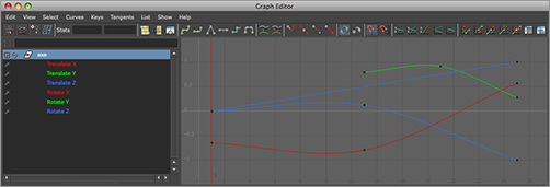
Figure 8-19: The Graph Editor displays the axe’s animation curves.

The curves in the Graph Editor represent the values of the axe’s position and rotation at any given time. The three axes are in their representative red, green, or blue color, and the specific attributes are listed much as they are in the Outliner in the left column. Selecting an object or an attribute on the left displays its curves on the right.
You should also notice that the curves are all at different scales. The three rotate curves range in value from about –45 to 45, the Translate Y curve ranges from about 15 to 5, and Translate Z looks flat in the Graph Editor. It’s tough to edit a curve with low values and still be able to see the timings of a larger value curve.
You can select the specific attribute and zoom in on its curve to see it better, or you can normalize the curves so that you can see them all in one view, with all their values in check. Click the Enable Normalized Curve Display icon in the top icon bar of the Graph Editor (![]() ). Doing so normalizes the view of all the curves within a scale of –1 to 1 to allow you to see the relative movement of all the curves at once.
). Doing so normalizes the view of all the curves within a scale of –1 to 1 to allow you to see the relative movement of all the curves at once.
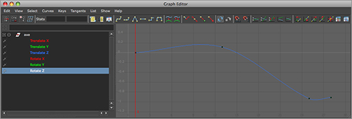
Figure 8-20 shows the Graph Editor from Figure 8-19 after the curves have been normalized. Keep in mind that this doesn’t change the animation in the slightest. All it does is allow you to see all the curves and their relative motion. You can denormalize the view by pressing the Disable Normalized Curve Display icon in the Graph Editor (![]() ). Normalizing your view is particularly helpful in busy scenes when you want to adjust the smallest scale of values alongside the largest scale of values without having to zoom in and out of the Graph Editor constantly to see the appropriate curves.
). Normalizing your view is particularly helpful in busy scenes when you want to adjust the smallest scale of values alongside the largest scale of values without having to zoom in and out of the Graph Editor constantly to see the appropriate curves.
Figure 8-20: The normalized view in the Graph Editor lets you see all the curves of an animation together in the same scale.
Notice that the Scale attributes on the axe aren’t shown in this window; only animated attributes appear here.
Also notice that the curve for Translate Y has keyframes only at frames 1 and 40. The animation dips in the first 15 frames because there is no keyframe at frame 15 as there is for Translate Z. That dip wasn’t there before you set the end keyframe at frame 40.
Continue the exercise by fixing this issue:
1. Move the first keyframe of Translate Y from frame 1 to frame 15 to fix the dip:
- Press W to activate the Move tool in Maya, or click the Move Nearest Picked Key Tool icon (
 ) in the Graph Editor.
 - Click the Time Snap On/Off icon (
 ) to toggle it on.
 - Select the offending Translate Y keyframe at frame 1, and MMB+click and drag it to the right until it’s at frame 15.
Scrub your animation, and the backward movement looks as it did before. You might have prevented this problem by manually setting your keyframes for the axe instead of using Auto Keyframe. The more you work with Maya, the more valuable you’ll find Auto Keyframe (although plenty of people get by without it just fine).
The axe now needs an arc on its way to the target.
2. Go to the middle of the axe’s flight, frame 27.
3. Move the axe up in the Y-axis a bit using the green handle of the Tool manipulator.
If the axe is slightly rotated in frame, Auto Keyframe can set a key for both Translate Y and Translate X, although you were perhaps expecting only a key in Translate Y. Because the Move tool is on the axe’s Local axis, and because the axe was slightly rotated at frame 27, there is a change in the Y and X positions in the World axis, which is the axis represented in the Graph Editor.
4. Select the Translate X key at frame 27, if one was created, and press Delete to delete it.
5. Now you’ll add a full spin to the axe to give the animation more reality and life. You can spin it in one of two ways:
- Go to frame 40, select the axe, and rotate it clockwise a full 360 degrees positive. Auto Keyframe enters a new rotation value at frame 40, overwriting the old value. You should see the Rotate Z curve angle down steeply as soon as you let go of the Rotate manipulator.
- In the Graph Editor, make sure you’re at frame 40, grab the last keyframe on the Rotate Z curve, and MMB+click and drag it down, probably past the lower limit of the window. If you keep the middle mouse button pressed as you move the mouse, the keyframe keeps moving as you move the mouse, even if the keyframe has left the visible bounds of the Graph Editor.
If you hold down Shift as you MMB+click and drag the keyframe to move it in the Graph Editor, the keyframe will move in only one axis (up or down, left or right).
By moving the keyframe down, you change the Rotate Z value to a lower number, which spins the axe clockwise. Before you try that, though, move your Graph Editor window so you can see the axe in the Perspective window. As you move the Rotate Z keyframe down in the Graph Editor, you see the axe rotate interactively. Move the keyframe down until the axe does a full spin.
6. Play back the animation by clicking the Play button in the playback controls. If your animation looks blazingly fast, Maya’s playback speed is probably set to Play Every Frame. Open the Animation Preferences window by clicking its icon (![]() ), and set Playback Speed to Real-Time (30fps).
), and set Playback Speed to Real-Time (30fps).
Changing the playback speed of an animation through the Animation Preferences window doesn’t alter the timing of your animation. It only changes the speed at which Maya plays the animation back to you in its windows. To change the playback speed, choose Window ⇒ Setting/Preferences ⇒ Preferences to open the Preferences window, choose Settings ⇒ Working Units, and select the proper setting.
Now, when you play back the animation, it should look slow. Maya is playing the scene back in real time, as long as the options in the Animation Preferences window are set to play back properly at 30fps. Even at 30fps, the scene should play back slowly, and this means the animation of the axe timing is too slow.
7. All you need to do is tinker in the Graph Editor a bit to get the right timing. For a good result in timing, move the first set of keyframes from 15 to 13. Then, grab the Translate Y keyframe at frame 27 and move it to 19. Finally, grab the keyframes at frame 40 and move them all back to frame 25. Play back the scene.
Adding Follow-Through
Load the axe_v4.mb file from the Axe project on the CD, or continue with your own file.
The axe is missing weight. Nothing much in this scene indicates that this is a heavy axe. You can add some finesse to the scene using follow-through and secondary motion to give more weight to the scene.
In the axe scene, follow-through motion is the axe blade driving farther into the target a little beyond its initial impact. Secondary motion is the recoil in the target as the momentum of the axe transfers into it. As you increase the amount of follow-through and secondary motion, you increase the axe’s implied weight. You must, however, walk a fine line; you don’t want to go too far with follow-through or secondary motion. The Graph Editor is great for adding these nuances to the axe. Follow these steps:
1. Select the axe in the scene using its selection handle, and open the Graph Editor.
2. Because you’ll add three frames to the end of this animation for follow-through, go to frame 28 (25 being the end of the current animation).
3. In the Perspective window, rotate the axe another 1.5 degrees in the Z-axis.
4. Rotating the axe in step 3 moves the axe’s blade down a bit in the Y-axis. To bring the axe back up close to where it was before the extra rotation, move the axe up slightly using the Translate Y manipulator handle. This also digs the axe into the target a little more. You’ll see a keyframe for Translate Y and most probably for Translate X, as well as Rotate Z.
If you play back the animation, the follow-through doesn’t look good. The axe hits the target and then digs into it as if the action were done in two separate moves by two different animators who never talked to each other. You need to smooth out the transition from the axe strike and its follow-through in the Graph Editor.
5. Highlight the Rotate Z attribute in the Graph Editor to get rid of the other curves in the window. Figure 8-18 shows the Rotate Z curve of the axe after the follow-through animation is added.
6. Focus on the last three frames of the curve, and zoom into that range only. The curve, as it is now, dips down past where it should and recoils back up a small amount.
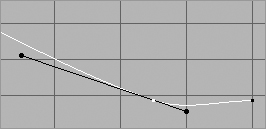
When you set keyframes, you create animation curves in the Graph Editor for the axe. These curves are Bézier splines, which stay as smooth as possible from beginning to end. When you set the new keyframe, rotating the axe about 1.5 more degrees for follow-through, the animation curve responds by creating a dip, as shown in Figure 8-21, to keep the whole curve as smooth as possible.
Figure 8-21: The normalized Rotate Z curve of the axe after the follow-through animation
Secondary Motion and Follow-Through
Secondary motion in animation comprises all the little things in a scene that move because something else in the scene is moving. For example, when a superhero jumps from a tall building and his or her cape flutters in the wind, the cape’s undulation is secondary motion.
Follow-through is the action in animation that immediately follows an object’s or a character’s main action. For example, after the superhero lands from their jump, his or her knees buckle a little, and the superhero bends at the waist, essentially squashing down a bit. That squashing motion is follow-through. The more follow-throughs, the more cartoon-like the animation appears.
The axe needs to hit the target with force and dig its way in, slowly coming to a stop. You need to adjust the curvature of the keyframes at frame 25 by using the keyframe’s tangents. Tangents are handles that change the amount of curvature influence of a point on a b-spline (Bézier spline). Selecting the keyframe in question reveals its tangents. (See Figure 8-22.)
Figure 8-22: The tangent handles of a keyframe. The handle to the left of the keyframe is the In tangent, and the handle to the right is its Out tangent.
7. Select the Out tangent for the Rotate Z attribute’s key at frame 25, and MMB+click and drag it up to get rid of the dip. Notice that the tangency for the In tangent also changes.
8. Press Z to undo your change. You need to break the tangent handles so that one doesn’t disturb the other.
9. Select the Out handle, and click the Break Tangents icon (![]() ) to break the tangent.
) to break the tangent.
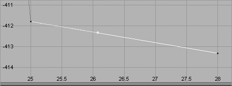
10. Move the handle up to get rid of the dip so that the curve segment from frame 25 to frame 28 is a straight line, angled down. Figure 8-23 is zoomed into this segment of the curve after it’s been fixed.
Figure 8-23: Zoomed into the end segment of the Rotate Z animation curve after the dip is fixed
Now, to get the axe to stop slowly as it digs into the target, you need to curve that end segment of the Rotate Z curve to flatten it out.
Figure 8-24: Zoomed into the end segment of the Rotate Z animation curve. Notice how the curve now smoothly comes to a stop by flattening out.

11. Grab the last frame to reveal its handles. You can manually move the In handle to make it horizontal, or you can click the Flat Tangents icon (![]() ) on the left side of the icon bar, under the menus in the Graph Editor.
) on the left side of the icon bar, under the menus in the Graph Editor.
The curve’s final segment for Rotate Z should now look like Figure 8-24.
Figure 8-25: Smoothed translate curves to ease out the motion
12. Adjust the keyframe tangents similarly for the axe’s Translate Y and Translate X curves. (See Figure 8-25.)
13. Play back the animation, and you should see the axe impact the target and sink into it a bit for its follow-through.
Now, you need to polish things up more.
Adding Secondary Motion
Load axe_v5.mb from the Axe project on the CD, or continue with your own scene file.
For secondary motion, you’ll move the target in reaction to the impact from the axe’s momentum.
An object in motion has momentum. Momentum is calculated by multiplying the mass of an object by its velocity. So, the heavier and faster an object is, the more momentum it has. When two objects collide, some or all momentum transfers from one object to the other.
In a game of pool, for example, when the moving cue ball collides with a stationary eight ball, the cue ball transfers some of its momentum into the eight ball, setting it in motion; the cue ball uses the rest of its own momentum to ricochet off in another direction.
In the axe scene’s impact, the axe lodges in the target, and its momentum is almost fully transferred to the target. But because the target is much more massive than the axe, the target moves only slightly in reaction. The more you make the target recoil, the heavier the axe will seem.
First, group the axe’s parent node under the target’s parent node. The axe will be left behind to float in midair if you animate the target’s parent node without grouping the axe under it. By grouping the axe under the target, you’ll move the target to recoil while keeping the axe lodged in it. The animation on the axe won’t change when you group the axe and target under a new node.
Grab the parent node of the target (called Target), and reset its attributes to 0 by freezing its transforms as you did with the ball. This sets the target node’s Translate and Rotate attributes back to 0 and its Scale attributes back to 1:
Figure 8-26: The front panel display of the target reacting to the impact of the axe

1. To freeze the transforms, select the target node, and then choose Modify ⇒ Freeze Transformations.
2. In the Outliner, MMB+click and drag the axe node to the target node to group it under. You can also MMB+click and drag the nodes in the Hypergraph to group the axe node under the target node.
3. Go to frame 25, the moment of impact, and set the position and rotation keyframes on Target.
4. Go to frame 28, rotate the target node in the Z-axis about 2.5 degrees, and move it up and back slightly in the Y and X axes, as shown in Figure 8-26.
5. Go to frame 31. Rotate the target node back to 0 in the Z-axis, move it down to 0 in the Y-axis, and move it back a bit more in the X-axis.
6. Go to frame 35 and repeat step 4, but only move it half as much in Rotate Z, Translate X, and Translate Y.
7. Go to frame 40 and repeat step 5, but move Target back only slightly in the X-axis.
If you don’t freeze the transforms on the target’s parent node before grouping the axe under it, the axe’s animation will change and yield undesirable results.
The preceding steps should give you an animation similar to axe_v6.mb in the Axe project on the CD.
Motion Trails
You can see a moving object’s trajectory, or motion trail—that is, its path of motion. Follow these steps:
1. Select the axe through its selection handle, and then choose Animate ⇒ Create Motion Trail ❒. (See Figure 8-27.)
Figure 8-27: The Motion Trail Options window
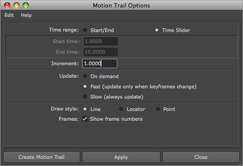
2. Select Line for Draw Style, and make sure the Show Frame Numbers check box is checked.
3. Click Apply, and then click Close to close the window.
The motion trail is useful for fine-tuning motion. Editing the animation curves in the Graph Editor and watching the motion trail adjust in the work panels shows you the precise trajectory of the axe throughout its movement. Play back your animation a few times to get a good sense of how the scene looks.
4. Select the axe, and open the Graph Editor.
5. Try adding more arc to the axe in the middle of its trajectory to the target.
6. In the Graph Editor, focus on the Translate Y curve, and select the keyframe at frame 19.
7. Move the keyframe up about 2 units, and watch the motion trail adjust to show you the higher arc.
8. Replay the animation with the higher arc in the middle.
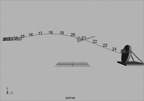
Notice that the axe seems a little more solid than before. The extra height in the trajectory really helps give the axe more substance. Figure 8-28 shows the axe and its motion trail after more height is added to its arc.
Figure 8-28: The axe and its motion trail
You can toggle the frame-number display on/off and change the display type of the motion trail from curve to points or locators through the motion trail’s Attribute Editor. To get rid of the motion trail, select it and press Delete.
Path Animation
As an alternative to keyframing the position of the axe, you can animate it on a path. Path animation allows you to assign an object to move along the course of a curve, called a path.
Load axe_v7.mb from the Axe project on the CD. This is the finished axe animation. You’ll delete most of your hard work by removing the translation animation on the axe, but you’ll keep the rotation and everything else. You’ll replace the translation keyframes you set up with a motion path instead. Follow these steps:
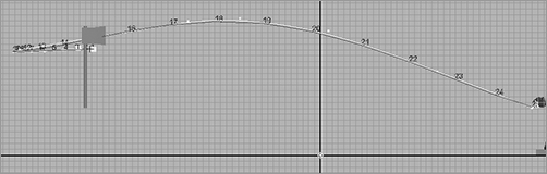
1. In the front window, and with the motion trails turned on, trace the motion trail with a CV curve (choose Create ⇒ CV Curve Tool) from the beginning of the trail to the end, as shown in Figure 8-29. Make sure the CV Curve tool is set to make cubic (3) curves.
Figure 8-29: Trace the motion trail.
2. Take note of the frames on which you set important keyframes for the axe’s position (for example, when it recoils and releases at frame 10 and when it hits the target at frame 25). Select the axe’s top node (axe), and delete its translation animation. Select all three Translate attributes in the Channel Box, and right-click to display the shortcut menu. Choose Break Connections to delete the animation from those channels. The axe now spins around, and it and the target recoil at the moment of impact, but the axe doesn’t actually move.
3. Keep the motion trail in the scene for now to help with the timing you’ve already created.
4. Select the top axe node, and then Shift+select the path curve. In the Animation menu set, choose Animate ⇒ Motion Paths ⇒ Attach to Motion Path ❒.
5. In the Options window, turn off the Follow check box.
The Follow feature orients the object on the path so that its front always points in the direction of travel. Because the axe moves backward in anticipation before it’s thrown forward, Follow would cause it to turn around twice, so turn this option off.
Now the axe will follow the curve end to end from frame 1 to frame 60. Of course, you have to adjust the timing to fit it, as before.
6. Select the motion trail, and move it down in the window to get it out of the way; but keep it lined up vertically with the path curve so you can figure out the timing again.
The file axe_path_v1.mb in the Axe project will bring you up to this point.
7. Select the top axe node, and open the Graph Editor to see the axe’s curves. The rotation curve is still intact, although the translation curves are missing. Click motionPath1 in the Channel Box to highlight it; the motionPath1.U Value curve that took the place of the translation curves appears in the Graph Editor. On the left side of the Graph Editor, select the motionPath1.U Value curve to display only that. Zoom into it. (Press A to view all.)
8. The curve is an even, linear curve from 1 to 60. You need the axe to hit at frame 25, so move the end of the curve to frame 25 from frame 60.
9. Retime the backward movement. Scrub the animation until the axe moves all the way back (frame 4). Using the Insert Keys tool (![]() ), insert a keyframe at frame 4. Select the animation curve, click the tool, and MMB+click the curve to create a key on it. You can MMB+click and drag the cursor to place the key precisely at frame 10 before releasing the mouse button.
), insert a keyframe at frame 4. Select the animation curve, click the tool, and MMB+click the curve to create a key on it. You can MMB+click and drag the cursor to place the key precisely at frame 10 before releasing the mouse button.
10. Move this new keyframe to frame 10 (the frame where backward movement originally ended).
11. Scrub the animation, and the timing is just about right. You’ll have to adjust the tangents a bit to make the axe move more like before, but the movement is essentially there with path animation.
The file axe_path_v2.mb in the Axe project will bring you up to this point.
Path animation is extremely useful for a number of tasks, but particularly for animating an object along a particular course. By adjusting the resulting animation curve in the Graph Editor, you can readjust the timing of the path animation easily.
A good path-animation exercise is to create an atom and draw CV curves around the nucleus for the paths of the electrons. Then, animate all the electrons orbiting the nucleus with the paths. Also, try reanimating the Solar_System exercise with paths instead of the keyframes you set on the rotations.
Ghosting
To see the position of an animated object a few frames before and after its current position, you can enable ghosting in Maya. For example, select the animated axe in your scene and, in the Animation menu set, choose Animate ⇒ Ghost Selected. Maya will display the axe’s three frames before and after the current time. To turn off ghosting, choose Animate ⇒ Unghost Selected.
Axe Project Summation
In the Axe example, you furthered your use of layered animation by beginning with the gross animation to cover the basic movements of the axe. After those timings were set, you completed most of the remaining work in the Graph Editor by moving keyframes here and there to add detail to the motion. You added more keyframes to create follow-through and secondary movement to insinuate weight into the axe and target.
Without secondary movement in the target, the axe would seem to weigh nothing. With too much movement, however, the axe would seem too heavy, and the scene wouldn’t look right. Subtle nuances can make stunning differences in the simplest of animations. You also went back into the animation and replaced the animation method entirely with path animation. This illustrates the multiple ways to accomplish a task in Maya; finding your own comfort zone with a workflow is one of the goals in learning Maya.