
As you’ve learned, you can easily create complex models by adjusting existing, simpler poly objects with some of the poly editing tools that Maya provides. Here’s a brief preview of what to expect in the world of poly editing. You should experiment with each tool on a primitive sphere as it’s introduced, so saddle up to your Maya window and try each tool as you read along.
Later in this chapter, you’ll deploy these new skills on two different poly models. In Chapter 6, “Practical Experience,” you’ll create a red wagon to exercise your modeling skills. For most of the work in this chapter, you’ll use the Polygons menu. Open the Edit Mesh menu, tear it off, and place it somewhere on your screen so you can get a good look at the tools and functions. You can access all of the following tools from that menu.
The Poly Extrusion Tools
The most commonly used poly editing tool has to do with extrusion. You can use Extrude to pull out a face or an edge of a polygon surface to create additions to that surface. You access the tool at Edit Mesh ⇒ Extrude. Maya distinguishes between edge or face Extrude based on whether you’ve selected edges or faces. Follow these steps:
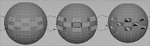
1. Select a face or multiple faces of a polygon, and choose Edit Mesh ⇒ Extrude. The regular manipulator changes to a special manipulator, as shown in the left image in Figure 4-10.
2. Grab the Z-axis move handle (the blue arrow), and drag it away from the sphere, as shown in the center of Figure 4-10.
3. Using the scale handles (the boxes) scales the faces of the extrusion. The cyan circle rotates the face. The image at right in Figure 4-10 shows the faces extruded, rotated, and scaled.
4. Choosing the Extrude command again without deselecting the faces lets you extrude even more, keeping the original extrusion shape and building on top of that.
5. Selecting the edges of the poly surface instead of the faces and choosing Edit Mesh ⇒ Extrude extrudes flat surfaces from the edges selected. The special manipulator works the same way as Extrude does for poly faces.
Figure 4-10: Extruding several faces at once on a sphere. The left image shows the selected faces, the middle image shows those faces extruded, and the right image shows those faces extruded with a rotation and smaller scale.
The face(s) you select pull out from the sphere, and new faces are created on the sides of the extrusion(s). The Extrude tool is an exceptionally powerful tool in that it allows you to easily create additions to any poly surface in any direction. It’s particularly useful for modeling characters and creatures. Later in this chapter, you’ll use it to make a simple human hand.
You can also use the direction and shape of a curve to extrude faces. Create a curve in the shape you want your extrusion to take, select the curve along with the face(s), and choose Extrude ❒. Taper decreases or increases the size of the face as it extrudes. Twist rotates the face as it extrudes, and Divisions increases the smoothness of the resulting extrusion. When you have your settings for those attributes, click Use Selected Curve For Extrusion (see Figure 4-11).
Figure 4-11: Extruding a face along a path curve

This seems to be strange behavior, but the Twist and Taper values are taken into account in the extrusion. You can edit these values when you uncheck Use Selected Curve For Extrusion, or you reselect this option after you enter values for Twist and Taper. If your faces aren’t extruding to the shape of the curve, increase the number of divisions.
The Wedge Face Tool
Similar to extruding faces, Wedge Face pulls out a poly face, but it does so in an arc instead of a straight line. For this tool, you need to select a face and an edge of the selected face for the pivot point of the corner. Here’s how to do this.
Select a face, Shift+select one of its edges, and choose Edit Mesh ⇒ Wedge Face ❒. (To select a face and Shift+select an edge, right-click the sphere to display the marking menu. Choose Face, and select a face. Right-click again, and choose Edge on the marking menu. Then, Shift+select one of the face’s edges.)
Figure 4-12: Executing a Wedge Face on a face of a sphere
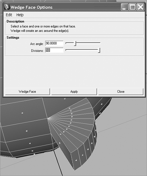
In the option box, you’ll notice some help for the tool under the Description heading. Under the Settings heading, you can select the degree of turn in the arc angle (90 degrees is the default) as well as the number of faces used to create the wedge (by moving the Divisions slider), as shown in Figure 4-12.
To access selection filters more easily, you can right-click an object to display a marking menu. Drag the cursor in the direction of the selection type you want, and release the mouse button. Then, click or Shift+click your selection.
The Wedge Face tool is useful for items such as elbows, knees, archways, and tunnel curves.
The Poke Face Tool
Poke Face is great for creating detailed sections of a mesh (poly surface) and bumps or indentations. To use the Poke Face tool to add detail to a face, select a face, and then choose Edit Mesh ⇒ Poke Face.
Figure 4-13: Poke Faces helps create areas of detail in your model.

A vertex is added to the middle of the face, and the Move manipulator appears on the screen, as shown in Figure 4-13. This lets you move the point to where you need it on the face. You can add bumps and depressions to your surface as well as create regions of extra detail. By selectively adding detail, you can subdivide specific areas of a polygon for extra detailed work, leaving lower poly counts in less-detailed areas for an efficient model.
The Bevel Tool
Use the Bevel tool to round sharp corners and edges. The Bevel tool requires that you select an edge or multiple edges and then use them to create multiple new faces to round that edge or corner.
Select an edge or edges, and choose Edit Mesh ⇒ Bevel ❒ to adjust your bevel. The Width slider sets the distance from the edge to the center of where the new face will be. This basically determines the size of the beveled corner. The Segments number defines how many segments are created for the bevel: the more segments, the smoother the beveled edge. Leaving Segments at 1 creates a sharp corner. See Figure 4-14.
Figure 4-14: Increase Segments to create a rounder corner.
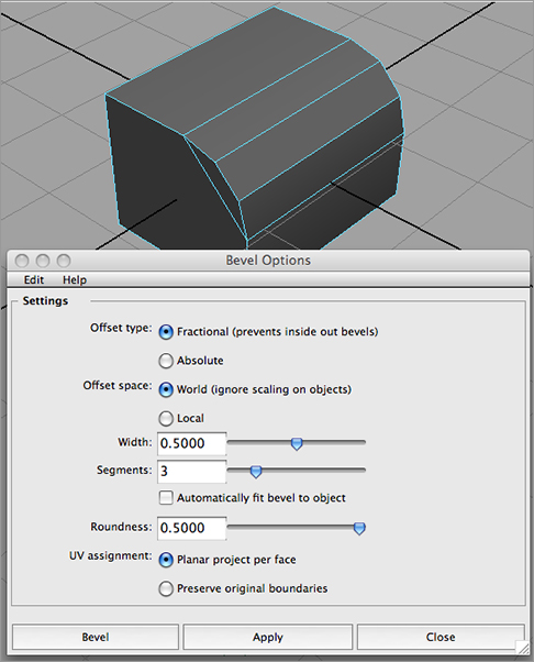
Figure 4-15: A poly bevel’s roundness set too high

The setting of the Roundness slider specifies the roundness of the corner. Setting the number too high will make the beveled edge stick out, as shown in Figure 4-15, although that can be a valid design choice. You can allow Maya to set the roundness automatically based on the size of the geometry being beveled. Select the Automatically Fit Bevel to Object check box to disable the Roundness slider. Move the Segments slider to set the number of new faces that are created on the bevel: the more segments, the smoother the bevel.
Use the Bevel tool to round polygonal edges. You can also use it to add extra surface detail, because Bevel creates more faces on the surface.
Having even a slightly rounded edge on a model—a box, for example—greatly enhances the look of that box when it’s lighted and rendered, because the edges catch much more light, helping define the shape of the box. A perfectly flat corner with no bevel doesn’t catch any light, making the model look weaker.