
Doing Dimensions with Style(s)
Creating a usable dimension style that gives you the dimension look you want is the biggest challenge in using AutoCAD's dimensioning features. Each drawing contains its own dimension styles, so changes you make to a dimension style in one drawing affect only that drawing. However, after you get the dimension styles right in a drawing, you can use it as a template or starting point for later drawings.
A dimension style (or dimstyle for short) is a collection of drawing settings called dimension variables, which are a special class of the system variables that I describe in Chapter 26.
You can create dimension styles with the annotative property — the steps to creating both annotative and non-annotative dimension styles are spelled out in the following sections. Although it's possible to change individual non-annotative dimensions to annotative in the Quick Properties or the Properties palettes, it's far more efficient to assign the annotative property to a dimension style so that all dimensions created in that style will be annotative.
Borrowing existing dimension styles
If you're lucky enough to work in an office where someone has set up dimension styles that are appropriate for your industry and project, you can skip the pain and strain of creating your own dimension styles. Bear in mind, however, that since annotative objects were introduced in AutoCAD 2008, dimension styles copied from pre-AutoCAD 2008 drawings are not going to be annotative. If the ready-made dimension style that you need happens to live in another drawing, you can use the DesignCenter palette to copy it into your drawing. For a refresher on using DesignCenter, see the sections “Using AutoCAD DesignCenter” and “Copying layers between drawings” in Chapter 6 — just substitute Dimstyles.
Creating and managing dimension styles
If you do need to create your own dimension styles or you want to tweak ones that you copied from another drawing, use the Dimension Style Manager dialog box, as shown in Figure 14-4.
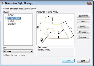
Figure 14-4: Yet another manager, this one for dimension styles.
Every drawing comes with a default dimension style named Standard (for imperial [feet-and-inches] drawings) or ISO-25 (for metric drawings). Although you can use and modify the Standard or ISO-25 style, I suggest that you leave them as-is and create your own dimension style(s) for the settings that are appropriate to your work. This approach ensures that you can use the default style as a reference. More important, it avoids a potential naming conflict that can change the way your dimensions look if the current drawing gets inserted into another drawing. (Chapter 17 describes this potential conflict.)
New drawings created in AutoCAD 2012 or AutoCAD LT 2012 using either the imperial template (acad.dwt or acadlt.dwt in AutoCAD LT) or the metric template (acadiso.dwt or acadltiso.dwt in LT) contain two dimension styles. As noted previously, imperial drawings have a style named Standard, and metric drawings sport a style named ISO-25; in addition, both have a style called Annotative. The Annotative style is a clone of Standard or ISO-25 with the single difference being the values of the overall scale factor (also known as the DIMSCALE system variable).
The following steps describe how to create your own dimension style(s):
 On the Ribbon's Home tab, click the label of the Annotation panel to open the panel slideout, then click the Dimension Style button.
Alternatively, if that just sounds like too much work, you could type D and press Enter. The Dimension Style Manager dialog box appears.
- In the Styles list, select the existing dimension style whose settings you want to use as the starting point for the settings of your new style.
For example, select the default dimension style named Standard or ISO-25.
- Click the New button to create a new dimension style that's a copy of the existing style.
The Create New Dimension Style dialog box appears.
- Enter a New Style Name and select or deselect the Annotative check box. Click Continue.
Select the Annotative check box to create an annotative dimension style, or deselect it for a non-annotative style. Refer to Chapter 13 for more about annotative objects.
The New Dimension Style dialog box appears. (This dialog box is virtually identical to the Modify Dimension Style dialog box shown in Figure 14-5 in the following section.)
- Modify dimension settings on any of the seven tabs in the New Dimension Style dialog box.
See the descriptions of these settings in the next section of this chapter.
- Click OK to close the New Dimension Style dialog box.
The Dimension Style Manager dialog box reappears.
- Click Close.
The Dimension Style Manager dialog box closes, and your new dimension style becomes the current dimension style that AutoCAD uses for future dimensions in this drawing.
- Draw some dimensions to test your new dimension style.
 Avoid changing existing dimension styles that you didn't create unless you know for sure what they're used for. When you change a dimension style setting, all dimensions that use that style change to reflect the revised setting. Thus, one small dimension variable setting change can affect a large number of existing dimensions! To play it safe, instead of modifying an existing dimension style, create a new style by copying the existing one and modifying the new one.
 A further variation on the already convoluted dimension styles picture is that you can create dimension substyles (also called style families) — variations of a main style that affect only a particular type of dimension, such as radial or angular. If you open the Dimension Style Manager dialog box and see names of dimension types indented beneath the main dimension style names, be aware that you're dealing with substyles.
Adjusting style settings
After you click New or Modify in the Dimension Style Manager dialog box, AutoCAD displays a tabbed New Dimension Style or Modify Dimension Style dialog box (the two dialog boxes are identical except for the title bar) with a mind-boggling — and potentially drawing-boggling if you're not careful — array of settings. Figure 14-5 shows the settings on the Lines tab, which I've modified from the AutoCAD defaults to conform to one office's drafting standards.

Figure 14-5: Modifying extension line settings on the Lines tab.
Fortunately, the dimension preview that appears on all tabs — as well as on the main Dimension Style Manager dialog box — immediately shows the results of most setting changes. With the dimension preview and some trial-and-error changing of settings, you can usually home in on an acceptable group of settings. For more information, use the dialog box help feature: Just hover your mouse pointer over the setting that you want to know more about.
 Before you start messing with dimension style settings, it's important to know what you want your dimensions to look like when they're plotted. If you're not sure how it's done in your industry, ask others in your office or profession, or look at a plotted drawing that someone in the know represents as being a good example.
The following sections introduce you to the more important tabs in the New/Modify Dimension Style dialog boxes and highlight useful settings. Note that whenever you specify a distance or length setting, you should enter the desired plotted size. For dimensions created with annotative styles, these are the actual paper (plotted) sizes. For dimensions with non-annotative styles, AutoCAD scales all these numbers by the overall scale factor that you enter on the Fit tab.
Following lines and arrows
The settings on the Lines tab and the Symbols and Arrows tab control the basic look and feel of all parts of your dimensions except text. Use these tabs to change the type and size of arrowheads or the display characteristics of the dimension and extension lines.
Tabbing to text
Use the Text tab to control how your dimension text looks — the text style and height to use (see Chapter 13) and where to place the text with respect to the dimension and extension lines. You may want to change the Text Style setting from the default Arial TrueType font to the more traditional Romans.shx font. The default Text Height is too large for most situations — set it to 1/8″, 3mm, or another height that makes sense. Figure 14-6 shows one company's standard text settings.

Figure 14-6: Whip your dimension text into shape.
If you're not opposed to defacing books, get out a bright red marker and put a circle around this warning (unless you borrowed the book from the library, of course). Here goes: You must define the text style that you specify for a dimension style with a height of 0 in the Text Style dialog box. (See Chapter 13 for more information about variable-height and fixed-height text styles.) If you specify a fixed-height text style for a dimension style, the text style's height will override the Text Height setting in the New/Modify Dimension Style dialog boxes. Use a zero-height style to avoid the problem — and bear in mind that using nonzero-height text styles in dimensions is one of the most common mistakes made by new AutoCAD users.
Industry or company standards usually dictate the size of dimension text. (For example, 1/8″ or 3mm is common in the architectural industry.) In any case, make sure you pick a height that's not too small to read on your smallest check plot.
The Text tab in the New/Modify Dimension Style dialog box sports a View Direction option. When set to Left-to-Right, horizontal dimension text reads right-way-up, and vertical text reads from the right side of the drawing. This is nearly always what you want, but occasionally you might need to rotate an entire drawing view by 90 degrees so it fits your drawing sheet (maybe you draw elevator shafts?), and at such times, some of your dimension text may read the wrong way around. You can create a whole AutoCAD dimension style for this, and you can also modify the view direction of individual dimensions in the Properties palette (see Chapter 6 for more on object properties).
Getting fit
The Fit tab includes a bunch of confusing options that control when and where AutoCAD shoves the dimension text if it doesn't quite fit between the dimension lines. The default settings leave AutoCAD in “maximum attempt at being helpful” mode — that is, AutoCAD moves the text, dimension lines, and arrows around automatically so that things don't overlap. If these guesses seem less than satisfactory to you, try the modified settings shown in Figure 14-7: Select the Over Dimension Line, Without Leader radio button under Text Placement and the Draw Dim Line between Ext Lines check box under Fine Tuning. (You can always move the text yourself by grip-editing it, as I describe in the section “Editing dimension geometry,” later in this chapter.)
Even at its most helpful, AutoCAD sometimes makes a bad first guess about how you want your dimension text and arrows arranged. If you're having problems getting the look you want, don't flip your wig — flip your arrows to the other side of the dimension lines by selecting the dimension, and choosing Flip Arrow from the multifunction grip on the arrow.
Most important, the Fit tab includes the Annotative check box, as shown in Figure 14-7. Using annotative dimensions, as I recommend in this chapter, will make your dimensioning go a lot more smoothly!
Just as with text, as I explain in Chapter 13, you can choose one of three different methods for dimensioning your drawings:
- You can dimension in model space using annotative dimensions. Assign annotation scales to the dimensions, and they change size as you change Annotation scales on the status bar. I think this system has the most to offer both new and experienced users.

Figure 14-7: Keep Fit and don't forget the Annotative setting.
- You can dimension in model space using non-annotative dimensions. If your drawing includes areas of different scales, you can create multiple dimension styles, one for each scale. This is probably the least convenient — although the longest established — method, especially in a drawing with multiple scale views.
- You can dimension in paper space using either annotative or non-annotative dimensions. Select the Scale Dimensions to Layout radio button on the Dimension Style Manager's Fit tab and draw dimensions in a paper space layout.
I recommend that you get comfortable with annotative dimensioning in model space first. Later on, if you want to try dimensioning in paper space, look in the AutoCAD help system: From the Exchange window's Help page, choose User's Guide![]() Annotate Drawings
Annotate Drawings![]() Dimensions and Tolerances
Dimensions and Tolerances![]() Use Dimension Styles
Use Dimension Styles![]() Set the Scale for Dimensions. As for old-style (that is, non-annotative) dimensioning, it's still part of the program, and many offices will probably keep doing it that way for a while to come.
Set the Scale for Dimensions. As for old-style (that is, non-annotative) dimensioning, it's still part of the program, and many offices will probably keep doing it that way for a while to come.
The Use Overall Scale Of setting corresponds to the DIMSCALE system variable, and you'll hear AutoCAD drafters refer to it as such. When either Scale Dimensions to Layout (for paper space layout dimensioning) or Annotative (for rescalable model space dimensioning) is selected, DIMSCALE is automatically set to 0. For more information about additional dimension-scale options, look up the DIMSCALE system variable in the AutoCAD help system.
Using primary units
The Primary Units tab gives you highly detailed control over how AutoCAD formats the characters in the dimension text string. You usually want to set the Unit format and Precision and maybe specify a suffix for unitless numbers if it's not clear from your drawing what units you're using. You may also change the Zero Suppression settings, depending on whether you want dimension text to read 0.5000, .5000, or 0.5. (“Zero Suppression!” also makes a great rallying cry for organizing your fellow AutoCAD drafters.)
AutoCAD 2010 introduced an interesting tweak to dimension text: Dimension subunits. If the main unit of measure on your drawing is meters, rather than have a bunch of smaller distances dimensioned as, say, 0.450, you could create a centimeter subunit so that any dimension of less than 1 meter would be shown in centimeters. Now, in every office I've ever worked in, there's a very strict drafting standard that says that all dimensions on a drawing must be in the same units — in other words, in a drawing with meters as the dimension unit, 0.45 would be correct, and 45cm would be incorrect. Check your own office standards before you incorporate this feature, which you can find on the Primary Units tab of the New/Modify Dimension Style dialog box.
Other style settings
If your work requires that you show dimensions in two different systems of measure (such as inches and millimeters), use the Alternate Units tab to turn on and control alternate units. If your work requires listing construction tolerances (for example, 3.5 +/−0.01), use the Tolerances tab to configure the tolerance format that you want. Unlike subunits (described in the preceding paragraph), alternate units display both dimensions at once; subunits replaces one unit (say, meters), with another unit (say, centimeters).
The New/Modify Dimension Style dialog box Tolerances tab settings are for adding manufacturing tolerances (for example, +0.2 or −0.1) to the text of ordinary dimensions — the kind of dimensions I cover in this chapter. AutoCAD also includes a separate TOLERANCE command that draws special symbols called geometric tolerances. If you need these symbols, you probably know it; if you've never heard of them, just ignore them. Look up Geometric Tolerance dialog box in the AutoCAD help system for more information.