
Modifying to Make It Merrier
When you have a better view of your base plate (which I talk about in the preceding section), you can edit the objects on it more easily. In the following sections, you use the ARRAY command to add more anchor bolts, the STRETCH command to change the shape of the plate, and the HATCH command to add crosshatching to the column. (As always, I cover these commands in detail later in the book.)
Hip-hip-array!
Using the ARRAY command is a great way to generate a bunch of new objects from existing objects at regular angles or spacing. The array pattern can be rectangular (that is, columns and rows of objects), polar (in a circle around a center point, like the spokes of a wheel around its hub), or it can follow a path.
AutoCAD 2012 introduces a sophisticated new method of arraying objects — I explain it in detail in Chapter 18. In this chapter, I introduce the simpler, old-style array feature.
In this example, you use a rectangular array to create three additional anchor bolts:
- Type –ARRAY and press Enter (don't omit the hyphen!).
Typing a hyphen in front of a command name tells AutoCAD you want to use the command line rather than a dialog box to specify values for the array.
The old-style ARRAY command starts at the command line, and AutoCAD prompts you to select the objects you want to array.
- Click the anchor bolt and then click the nut.
 If you encounter any problems while trying to select objects, press the Esc key a couple of times to cancel the command; then restart the –ARRAY command and try again.
AutoCAD continues to prompt you at the command line:
Select objects: 1 found, 2 total
- Press Enter or right-click to end object selection.
You specify the parameters of an array by first telling AutoCAD whether you want a rectangular or polar (circular) array. A rectangular array creates regularly spaced rows and columns. Next you specify the number of rows and the number of columns, and then the spacing between rows and the spacing between columns.
AutoCAD prompts:
Enter the type of array [Rectangular/Polar] <R>:
- Type R and press Enter to accept a rectangular array.
AutoCAD prompts:
Enter the number of rows (---) <1>:
AutoCAD wants to know how many rows and columns you want. Because the source object is included in AutoCAD arrays, you must specify two rows and two columns of bolts.
- Type 2 and press Enter. At the next prompt for the number of columns, type 2 and press Enter again.
AutoCAD prompts:
Enter the distance between rows or specify unit cell (---):
Almost done! To complete the array you tell AutoCAD the spacing between rows and columns.
- Type 24 [600] and press Enter. At the Enter distance between columns prompt, type 24 [600] and press Enter again.
AutoCAD adds the additional objects to the drawing, as shown in Figure 3-11.
- If anything looks wrong, type U or click Undo to delete the array and start again.
Unfortunately, the command line is not as forgiving as a dialog box!
- Press Ctrl+S to save the drawing.

Perfect! Except that nutbar engineer has decided the column needs to be 18 × 18 inches [450 × 450 mm] instead of 12 × 18 inches [300 × 450 mm — unfortunately, there are just as many metric nutbars as imperial ones]. And that means the base plate is too small, and the anchor bolts are in the wrong place, too. If you were working on the drawing board, you'd be getting out an eraser right about now and rubbing out all your efforts. AutoCAD to the rescue!
 The drawing afd03c-i.dwg [afd03c-m.dwg] contained in the afd03.zip download adds the remaining anchor bolts.
Stretching out
The STRETCH command is powerful but a little complicated — it can stretch or move objects, depending on how you select them. The key to using STRETCH is specifying a crossing selection box properly. (Chapter 10 gives you more details about crossing boxes and how to use them with the STRETCH command.)
Follow these steps to stretch the column and base plate:
- On the Modify panel, click the Stretch button — the one with the corner of a rectangle being stretched.
The STRETCH command starts, and AutoCAD prompts you to select objects. This is one of those times (and one of those commands) that really does require you to look at the command line:
Select objects to stretch by crossing-window or crossing- polygon… Select objects: - Click a point above and to the right of the upper-right corner of the plate (Point 1 in Figure 3-12).
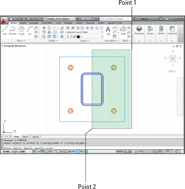
Figure 3-12: Specifying a crossing box for the STRETCH command.
- Move the crosshairs down and to the left.
The pointer changes to a dashed rectangle enclosing a rectangular green area, which indicates that you're specifying a crossing box. AutoCAD prompts you at the command line as follows:
Select objects: Specify opposite corner:
- Click a point below the plate, roughly under the center of the column (Point 2 in Figure 3-12).
The crossing box must cut through the plate and column in order for the STRETCH command to work (refer to Figure 3-12).
AutoCAD prompts you at the command line:
Select objects: Specify opposite corner: 7 found
Select objects:
- Press Enter to end object selection.
AutoCAD prompts you to specify the base point.
- If they're not already on, turn on Snap Mode, Ortho Mode, and Object Snap by clicking their respective buttons on the status bar until they appear highlighted.
- Move your mouse pointer over the lower-right corner of the plate, and click when you see a square box with an “Endpoint” tooltip.
This point serves as the base point for the stretch operation. Chapter 11 describes base points and displacements in greater detail.
AutoCAD prompts you at the command line:
Specify second point or <use first point as displacement>:
- Move the crosshairs to the right until the tooltip shows a displacement of 6 [150] units to the right, and then click in the drawing space (see Figure 3-13).
AutoCAD stretches the column and plate by the distance that you indicate and moves the anchor bolts that were completely inside the crossing window rectangle, as shown in Figure 3-13.
If your first stretch didn't work right, press Ctrl+Z and try again. STRETCH is an immensely useful command — one that makes you wonder how drafters used to do it all with erasers and pencils — but it does take some practice to get the hang of those crossing boxes. - Press Ctrl+S to save the drawing.

Figure 3-13: Stretching the base plate.
The drawing afd03d-i.dwg [afd03d-m.dwg] contained in the afd03.zip download is the stretched version of the base plate.
Crossing your hatches
Your final editing task is to add some crosshatching to the space between the inside and outside edges of the column to indicate that the drawing shows a section of the column. To do so, follow these steps:
- Turn off Snap, Ortho, and Object Snap Modes by clicking their respective buttons on the status bar until they look dimmed.
- Repeat Steps 2 through 7 from the “Drawing rectangles on the right layers” section (earlier in this chapter) to create a new layer named Hatch. Set its color to 6 (magenta) and make it the current layer.
- On the Home tab's Draw panel, click the Hatch button — the one that shows the fine crosshatching inside a square.
The Hatch Creation tab appears on the Ribbon. For more information on this tab, and hatching in general, see Chapter 15.
- In the Hatch Creation tab's Pattern panel, click the Hatch Pattern button and select ANSI31.
Depending on your screen resolution the panels may show more or less information. You may see an ANSI31 swatch without having to click the Hatch Pattern button.
As you move your crosshairs over the drawing objects, a live preview shows you the result if you click at the current crosshair position. AutoCAD prompts
Pick internal point or [Select objects/seTtings]:
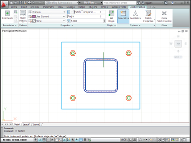
- Move the crosshairs so they're between the inside and outside edges of the column. Zoom in if you need to get closer.
The live preview shows the ANSI31 hatch pattern filling the space between the two filleted rectangles. Live preview not only shows you the pattern, it also lets you adjust hatch angle and scale. In this case, it looks like the hatch pattern may be too fine.
- In the Scale box of the Hatch Creation tab's Properties panel, change the value to 5 and press the Tab key to confirm it.
- Move your crosshairs back to the space between the two filleted rectangles to preview the hatch again. If it looks okay, click within the hatched area to confirm the hatch object, then press Enter to finish the command.
Your finished column and base plate looks like Figure 3-14.
- Click the tiny arrow below the Zoom button on the Navigation bar and choose Zoom All from the menu.
AutoCAD zooms out so that the entire area defined by the limits is visible.
- Press Ctrl+S to save the drawing.
After some drawing and editing, you may wonder how you're supposed to know when to turn off or on the various status bar modes (Snap, Grid, Ortho, Object Snap, and so on). You'll start to get an instinctive sense of when each mode is useful and when it gets in the way. In subsequent chapters of this book, I give you some more specific guidelines.
Drawing afd03e-i.dwg [afd03e-m.dwg] available in the afd03.zip download is the completed base plate. How does it compare with your version?