Adding the Third Dimension to 2D Objects
AutoCAD's 2D roots run deep. Drafting continues to be the primary focus of the program, but recent AutoCAD releases have shifted focus, and the program has become more and more adept at 3D modeling. This section invites you to take what you probably have an abundance of right now (2D objects) and create new 3D objects from them.
Creating 3D objects from 2D drawings
You can create 3D objects from 2D objects by using a number of different techniques. You can add thickness or extrude an open 2D object to create a surface, or take multiple 2D cross sections and create a lofted object that adapts to the shape and size of each cross section selected. Everything mentioned here applies to AutoCAD only (not AutoCAD LT), with the exception of the thickness property.
Add thickness to a 2D object
Most 2D objects, such as lines and circles, have a thickness property. Changing a 2D object's thickness property does not create a true 3D object, but it does create a pseudo-surface that looks like a 3D surface. These pseudo-surfaces can hide objects beyond them, but they do have limitations. If you add thickness to a circle, an open cylinder is created without caps on the top and bottom. You can also change the thickness of a polyline to create an open box that has no top or bottom.
Extrude open and closed objects
 Thickness is one way of adding height to an object, but extruding an object is usually a better approach. You can extrude open or closed 2D objects to create a 3D object. Extruding a closed 2D object, such as a polyline, spline, ellipse, circle, or region, creates a 3D solid; extruding an open 2D object, such as a polyline, spline, line, or arc, creates a surface. Figure 22-8 shows results of extruding open and closed objects.
To extrude an open or closed 2D object, click Extrude on the Solid panel of the Solid tab, or click the Extrude split button on the Home tab's Modeling panel (if you see a button labeled Loft, Revolve, or Sweep, click the lower part of the split button and choose Extrude from the drop-down menu). Use the MOde option to control whether you create a surface or 3D solid from a closed object, select the objects you want to extrude, and specify an extrusion height or distance to create the 3D solid.

Figure 22-8: 2D to 3D by extrusion is easy as 1, 2, 3.
 The DELOBJ system variable controls whether the 2D objects you use to create 3D solids is retained or erased. Most of the time, you probably want to keep the source geometry, but the default DELOBJ setting erases it. If you want to keep the original 2D geometry, type DELOBJ and set its value to 0. (See Chapter 26 for more about system variables.) DELOBJ also controls whether or not the source objects for associative arrays (introduced in Chapter 18) are retained or deleted.
Press and pull closed boundaries
 The PRESSPULL command allows you to create 3D geometry by extruding a closed boundary. PRESSPULL differs from EXTRUDE in that the EXTRUDE command requires 2D geometry while PRESSPULL can use closed boundaries formed by other 3D solids.
To press or pull within a closed boundary to create a 3D object, click Presspull on the Solid tab's Solid panel, and then click as required to specify a closed boundary. After you've clicked in a closed boundary, drag or specify the distance on the extrusion you want to create.
Loft open and closed objects
 Lofting allows you to select a series of 2D cross-sections to create a surface or 3D solid. The selected cross-sections are used to define the outer surface that's generated. You must select a minimum of two cross-sections. If you select open objects, the resulting loft is a surface; if you select closed objects, the resulting loft can be either a surface or 3D solid, depending on the current value of the MOde option for the LOFT command.
You can loft objects along a path using guide curves, or just between the selected cross-sections (see Figure 22-9). To loft open or closed 2D objects, open the Sweep/Loft drop-down on the Solid tab's Solid panel. Use the MOde option to control whether you create a surface or 3D solid from a closed object cross-sections, and specify how the loft object should be calculated.

Figure 22-9: Using cross-sections to created a lofted object
Sweep open and closed objects along a path
 Sweeping is similar to extruding a 2D object, except you specify a path, rather than a height or distance. The object used as the path can be either an open or closed 2D object, and can be only a single object (see Figure 22-10). If you sweep an open object, the resulting swept object is a surface; if you sweep a closed object, the resulting swept object is a surface or 3D solid based on the current value of the MOde option of the SWEEP command.
To sweep an open or closed 2D object, open the Sweep/Loft drop-down on the Solid panel of the Solid tab. Use the MOde option to control whether you create a surface or 3D solid from a closed object, select the objects to sweep, and specify a path for the sweep.

Figure 22-10: Sweeping a closed object along a path.
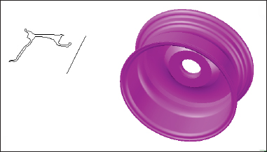
Revolve open or closed objects around an axis
 Revolving allows you to create a surface or 3D solid by turning selected objects around an axis (see Figure 22-11). If open objects are selected, the resulting revolved object is a surface; if you select closed objects, the resulting revolved object is a 3D solid.
To revolve an open or closed 2D object, click Revolve on the Solid panel of the Solid tab, or click the Revolve split button on the Home tab's Modeling panel (if you see a button labeled Loft, Extrude, or Sweep, click the lower part of the split button and choose Revolve from the drop-down). Use the MOde option to control whether you create a surface or 3D solid from a closed object, select the objects to revolve, and specify the axis to use.