
From Drawing to Modeling in 3D
This section introduces three techniques for creating 3D objects: drawing 3D lines and polylines, creating 3D objects from 2D geometry, and creating solids. (In AutoCAD LT you can use the first two techniques only.) AutoCAD is also very capable at surface modeling, offering both freeform mesh and NURBS surfaces. If you're interested in either of these, check out the online help system — navigate to User's Guide, then choose Work with 3D Models, and then Create 3D models. Topics include creating surfaces and meshes from scratch, and creating solids and surfaces from 2D objects.
 When you draw 3D objects, just like when you draw 2D objects, put them on appropriate layers and use precision techniques to specify each point and distance. (See Chapter 5 for more information.)
Drawing basic 3D objects
The most basic forms of 3D geometry are wireframe-like objects created by picking points or entering X,Y,Z coordinates. Such objects have no surfaces, so look the same in 2D Wireframe mode or a photorealistic rendering. They are most useful as paths for sweeps and lofts, or as edges for surface creation. Such objects include
- Lines. Lines are really 2D objects; although you can specify different z-coordinates for start- and endpoints so they are not coplanar with the world coordinate system, each individual segment is based on its own 2D plane. You can, however, use lines for constructing objects in 3D space.
- 3D Polylines. Created with the 3DPOLY command. Similar to the 2D polylines I describe in Chapter 8, except the vertices of 3D polylines can have different z-coordinates (2D polylines must be planar). 3D polylines are useful as paths for sweeps or for fly-throughs (I don't cover walk-throughs or fly-throughs in this book).
- Splines. Splines are freeform curves, created with the SPLINE command and I describe them in a 2D context in Chapter 9. Splines are 3D objects and vertices can have different z-values. Splines are a better option than 3D polylines for sweeps because they can have smoother curves.
- Helixes. Helixes can be either 2D (think of a mosquito coil, or the element on an electric range) or 3D (think of Mr. Slinky). Helixes are especially useful as paths for threaded objects.
You can find the LINE, 3DPOLY, and SPLINE commands on the Draw panel of the Ribbon's Home tab; the HELIX command is on that panel's slideout.
 The 3DPOLY command is similar to the PLINE (plain old 2D polylines) command. Both commands draw a series of connected line segments, but they have different capabilities:
- The 3DPOLY command accepts 3D points for the line segments' vertices. The PLINE command requires that all vertices be on the same plane.
- 3DPOLY is limited to straight line segments. PLINE can draw arc segments and create segments with uniform or tapered width.
- Segments created with 3DPOLY can't display dash-dot linetypes; 3D polyline segments always display as continuous lines.
The command sequence for drawing 3D segments with the LINE or 3DPOLY command is the same as for drawing 2D segments with the LINE or PLINE command; see Chapter 8 if you need a refresher on drawing lines. The only difference is that you specify 3D coordinates instead of 2D ones. Figure 22-6 shows an example.
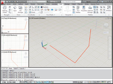
Figure 22-6: Entering 3D coordinates to draw a 3D polyline.
Creating 2D representations in this way is straightforward, though tedious for all but the simplest objects. More important, a wireframe model becomes increasingly difficult to decipher as the complexity of the model increases. You see a mass of lines representing the edges, and you have difficulty telling which parts of which edges are in front of others. To reduce this visual confusion, you need to graduate to surface or solid modeling commands. I introduce you to solid modeling in subsequent sections of this chapter.
Gaining a solid foundation
Solid modeling is in many ways the culmination of 3D CAD. Solids more accurately represent most real-world objects than do wireframes or surfaces. And even when representational accuracy isn't the main issue, it's easier to construct many kinds of models with solids.
Many special-purpose solid modeling programs use a combination of solid and surface modeling techniques for maximum flexibility in constructing and editing 3D models. These kinds of programs — and solid modeling in general — are becoming especially popular in mechanical design.
Constructing the basic building blocks — or solid primitives — for a solid model in AutoCAD isn't difficult. Just follow these steps:
- Define a suitable UCS (user coordinate system).
See the “Changing Planes” section in Chapter 21. The UCS controls the construction plane and basic 3D orientation of the solid.
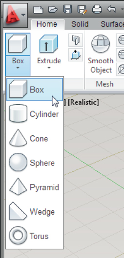
- Click the leftmost button on the Modeling panel of the Home tab, and then choose a solid primitive from the lower half of the split button.
As shown in Figure 22-7, your choices are Box, Cylinder, Cone, Sphere, Pyramid, Wedge, and Torus.
 When you see a 3D object in a drawing, you can't tell by looking whether it's a 2D extruded object, surface mesh, or solid. If you want to find out, open the Properties palette and select the object. The drop-down list at the top of the palette shows the type of object that you selected.
Drawing solid primitives
Solids are the easiest kind of object to work with if you're new to 3D. There are two types of 3D solid object:
- Primitive solids: The most basic of 3D building blocks, such as boxes, cones, and spheres. Primitive solids are based on simple geometric shapes like lines and circles.
- Complex (or compound) solids: Made by combining primitive solids and optionally editing them with Boolean operations. The following sections focus on creating and modifying 3D solids.
Boolean editing operations (named for the Victorian English mathematician George Boole) use arithmetic-like functions to combine solid objects or remove parts of them. The three primary Boolean commands in AutoCAD are UNION, SUBTRACT, and INTERSECT. See “Boolean operations” later in this chapter for more information.