
Getting Your 3D Bearings
The first challenge in 3D modeling is being able to see your three-dimensional model on a two-dimensional computer screen. The normal model space view on the Model tab in the drawing area shows a single, projected 2D view of your model — the top-down, “plan” view by default.
AutoCAD provides two model space capabilities that enable you to escape this visual flatland:
- With viewports, you can carve the model space drawing area into smaller rectangular areas, each of which shows a different view of the model.
- With viewpoints, you can change the point in 3D space from which you look at the model. By setting a different viewpoint in each viewport, you can look at several sides of your model at the same time. It's like looking at one of Picasso's cubist paintings, only what you see is more orderly.
No matter how much or how little 3D modeling you're thinking about doing, it's well worth your while to set up a template. (I fill you in on drawing templates in Chapter 4.) If you've ever started a new drawing, you're probably aware that AutoCAD already comes with a template for 3D modeling named acad3d.dwt (or acadiso3D.dwt for the metrically inclined). This is fine as far as it goes, but it only shows you a single view of your model. The next section explains how to improve on this template.
Creating a better 3D template
Model space viewports enable you to see several views of your model at one time, each from a different viewpoint. For this reason, model space viewports are especially useful when you're creating and editing objects in 3D. As you draw and edit, the different views help ensure that you're picking points that are located correctly in 3D space.
Chapter 5 discusses viewports in paper space, which are useful for creating layouts for use in plots and presentations in both 2D and 3D. Model space viewports, cousins of paper viewports, are less flexible but simpler, and are a great help in constructing 3D models.
Model space viewports divide the screen into separate rectangles with no gaps between them. Unlike with paper space viewports, you can't move, stretch, or overlap them. You can't plot multiple model space viewports (that's what paper space is for). And, unlike the situation in layouts, a layer that's visible in one model space viewport always is visible in all of them.
 You may hear or read references to tiled viewports, which is just another name for model space viewports. Tiled refers to the way in which model space viewports always fill the drawing area, with no gaps and no overlapping allowed. Conversely, paper space viewports are sometimes called floating viewports because you can move them around, leave gaps between them, and overlap them.
 One of the best new features in AutoCAD 2012 go by the somewhat obscure title of in-canvas viewport controls. Those little text labels that you may have noticed at the top-left corner of the graphics area (refer to Figure 22-1 for example) are clickable controls that let you set the visual style and the view. What's especially nifty is that double-clicking the plus or minus sign toggles the drawing area between multiple tiled viewports already configured for 3D viewing, and a single, maximized viewport. Out of the box, double-clicking the minus (−) sign switches to four equal sized viewports showing different views of the geometry. Figure 22-1 illustrates what I'm talking about: In this example, you see four viewports, four different viewpoints, and four different visual styles. That's a bit extreme for everyday work, but it gives you an idea of the possibilities.
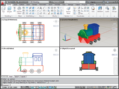
Figure 22-1: 3D viewing from every which way.
I highly recommend working with multiple viewports when you're modeling in 3D — that way you get to see exactly what you're doing in all three dimensions, in real time. My own preference is to work mostly in the isometric viewport, so I make that one larger than the other three. The in-canvas viewport toggle will switch back and forth between the last multiple viewport you set up, and a maximized viewport. In the following steps, I explain how to set up the tiled-viewport configuration you see in Figure 22-3.
- If you're not already in the 3D Modeling workspace, click the Workspace drop-down list in the Quick Access Toolbar and select 3D Modeling.
You can also click the Workspace Switching button on the status bar and again, select 3D Modeling. If the Materials Browser palette opens, close it.
- Click New on the Quick Access Toolbar to open the Select Template dialog box.
If a new blank drawing appears and you don't see the Select Template dialog box, someone has assigned a default template to this button in the Options dialog box. In that case, click the Application button (the Big Red A) and choose New, then choose Drawing from the submenu.
- Choose acad.dwt (choose acadiso.dwt if metric is your preference), and click Open.
Yes, I know there are ready-made 3D templates (acad3d.dwt and acadiso3d.dwt), but trust me — it's easier to start this setup from a 2D template.
 From the Viewports panel on the Ribbon's View tab, choose Named.
The Viewports dialog box appears.
- Click the New Viewports tab to make it current, then choose Four: Left (my preference) or Four: Right from the Standard Viewports list box.
The Preview panel shows a large, squarish viewport occupying most of the work area, with three small squarish viewports stacked on the left (or right). The default 2D setup shows the visual style of all four viewports as “2D Wireframe.” (I explain visual styles in Chapter 21.)
- From the Setup drop-down list, choose 3D.
The visual styles remain as 2D Wireframe, but the view direction (listed as “Current” in 2D Setup) is now SE Isometric in the large viewport, while the three small viewports show Top, Front, and Right orthographic views.
 When modeling in 3D, it's nearly always helpful to look at your objects in different ways at the same time. When looking at orthographic views, same as with a drafted drawing, you probably want to see all your linework. But you can get a better sense of the three-dimensionality of your model by looking at it in a shaded view. With multiple viewports, you can do both at the same time.
 - In the Preview area, click inside the large SE Isometric viewport, then choose Conceptual from the Visual Style drop-down.
You're almost finished in here. Rather than go through this setup every time you want to do some modeling, give your new viewport configuration a name.
- In the New Name box at the top of the Viewports dialog box, enter a name — V3D, for example — for the configuration.
Figure 22-2 shows the new, named viewport configuration. After you close the Viewports dialog box, you can restore this configuration at any time by clicking the Named Viewports tab, choosing V3D, and clicking OK.

Figure 22-2: Setting up a 3D work environment in the Viewports dialog box.
- Click OK to save the viewport configuration and close the Viewports dialog box.
In Figure 22-3, I've turned off the grid in the three small ortho viewports, but whether you leave it on or turn it off is a matter of personal preference.
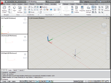
Figure 22-3: 2D and 3D all at the same time.
 The ViewCube's Home button can trip you up by changing to a view you don't expect. (I introduce the ViewCube in Chapter 21.) If you want to keep the current SE Isometric viewpoint, be sure to reset the Home view. And because you've gone to the trouble of setting up a shaded 3D viewport, why not make it a little more realistic and turn on perspective mode at the same time?
 - In the large 3D viewport, right-click the ViewCube to display its shortcut menu, then click Perspective With Ortho Faces (see Figure 22-4).
Selecting Perspective shows your orthographic views in perspective mode, and usually you don't want that. Selecting Perspective With Ortho Faces resets the projection mode from perspective to parallel when you switch to an orthographic view.
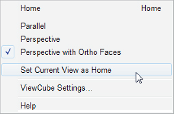
Figure 22-4: Changing settings in the ViewCube's right-click menu.
- Repeat Step 10, this time selecting Set Current View As Home.
Now you can readily return to this viewport configuration, keeping the same viewpoint in all viewports, perspective projection in the 3D viewport, and parallel projection in the orthographic viewports.
To return to a single viewport later, simply click the plus (+) sign on the in-canvas viewport control.
The last thing to do is save the configuration you've just set up as a template (.dwt) file.
- Click Save on the Quick Access Toolbar. On the Files Of Type drop-down menu, choose AutoCAD Drawing Template (*.dwt) and enter a filename. Click Save.
AutoCAD saves your new 3D template file in the same place as your other templates so it's always there for you to select when you want to do some serious 3D modeling.
Seeing the world from new viewpoints
When you choose 3D in the Viewports dialog box's Setup drop-down list, you direct AutoCAD to change the viewpoint in each viewport. The default viewpoints when you choose a four viewport arrangement are top, front, right, and SE (“southeast”) isometric. These viewpoints work well for viewing and constructing simple models, but eventually, you'll probably want to specify your own custom viewpoint in a particular viewport.
In both AutoCAD and AutoCAD LT, the best — but not the easiest — way to change viewpoints is to use the drop-down list on the Views panel of the View tab (as shown in Figure 22-5) to switch to one of the standard orthographic 3D views or an isometric view:
- The six standard orthographic (straight-on) views are Top, Bottom, Left, Right, Front, Back.
- The four standard isometric views are SW (left-front), SE (right-front), NE (right-back), and NW (left-back). An isometric view is one in which you see the object from above, but not too high above — as though you were hovering in a low-flying helicopter.

Figure 22-5: The preset views drop-down menu.
The easiest — but not the best — way to change viewpoints is to click one of the named faces on the ViewCube (not available in AutoCAD LT). I don't recommend this because the ViewCube is a viewing aid, and nothing but. You usually change to an orthographic view because you want to do some drawing or modeling there, and for that, your UCS (user coordinate system) ought to orient itself with the view (see Chapter 21 for the skinny on UCSs). Clicking Front on the ViewCube shows you a nice front view of your model, but it leaves the UCS unchanged, and that can make drawing anything difficult. Clicking Front on the View tab's Views panel does change the UCS to Front so it matches the view and lets you draw without difficulty.
These ten views are called “standard” because they're often used in manual drafting and rendering work. They work well for showing 3D models of common objects such as mechanical components and buildings. You can also change to plan view, which is a top-down view of either the world coordinate system or a user coordinate system. (I describe coordinate systems in Chapter 21.)
 The full version of AutoCAD has the ViewCube, the 3DORBIT command, and the Shift+Middle button method of changing 3D viewpoints (all are described in Chapter 21). AutoCAD LT's options are much more limited. LT users can set nonstandard viewpoints by typing DDVPOINT and pressing Enter. In the Viewpoint Presets dialog box that appears, specify the following settings:
- A viewing angle in the XY plane (imagine moving a camera on a dolly around an object, while keeping the camera at the same elevation)
- An angle from the XY plane (imagine using a boom to swoop the camera up to a different height so that you're looking at the object from increasingly steep angles)
AutoCAD users can set viewpoints the same way, but it's grossly inefficient compared to the other viewing options.
By default, AutoCAD shows 3D models in 2D wireframe mode, even if you've created surface or solid objects. If you want to better visualize which objects are in front of which other objects, especially in an isometric or other non-orthogonal view, you have a couple of options:
- Select a shaded visual style such as Realistic, Conceptual, X-Ray, or Shades of Gray, from the Visual Styles drop-down on the Visual Styles panel of the View tab. (See Chapter 21 for the low-down on visual styles.)
- Render the model, as described in Chapter 23.
AutoCAD LT doesn't include visual styles, because they're not much use in 2D drafting. A drawing saved in a visual style in the full version of AutoCAD does display that style when it's opened in AutoCAD LT — however, there's no way of changing it to 2D wireframe (or anything else) so you can actually work on it.