
Getting with the Program
In most of this book, I focus on 2D drafting, which is by far the easiest way of getting your feet wet with AutoCAD. (Just don't be dripping water on your computer.) And if you're not already in the Drafting & Annotation workspace, I suggest that you use the Workspace Switching button to return to it. After you make the switch to this workspace, AutoCAD displays the interface shown earlier in Figure 2-1.
Like all good Windows programs, AutoCAD has tooltips, those short descriptions that appear in little text boxes when you hover the mouse pointer over a button. In AutoCAD 2012, tooltips display two levels of information. When you hover the mouse pointer over a tool button, you first see a quick identification of the command. If you keep hovering, a longer description of the icon's function, often with a graphic image, appears in an extended tooltip. Helpful as they are when you're starting with AutoCAD, you'll probably want to remove these training wheels sooner or later. You can do so in the Options dialog box. (See the online help for more information.)
Looking for Mr. Status Bar
The application status bar (see Figure 2-6) appears at the bottom of the AutoCAD screen. The status bar displays and allows you to change several important drawing modes, aids, and settings that affect how you draw and edit in the current drawing. I introduce them in this section.
You can set status bar buttons to display icons or the traditional text labels that will be familiar to users of earlier releases. To switch from one style to the other, right-click any of the drawing mode buttons at the left side of the status bar and select or deselect Use Icons.

Figure 2-6: Status (bars) check.
Some of these status bar settings won't make complete sense until you've used the AutoCAD commands that they influence, but here's a brief description, with references to detailed descriptions of how to use each setting, starting at the left end of the status bar (and note that not all buttons are displayed at all times, so Figure 2-6 doesn't show all the buttons listed):
- Coordinates of the crosshairs: The coordinates readout displays the current X,Y,Z location of the crosshairs in the drawing area, with respect to the origin point (whose coordinates are 0,0,0). (AutoCAD LT displays only the X,Y crosshairs location.) Chapter 7 describes AutoCAD's coordinate conventions and how to use this area of the status bar.
 If the coordinates in the lower-left corner of the screen are grayed out, coordinate tracking is turned off. Click the coordinates so that they appear in dark numbers that change when you move the crosshairs in the drawing area.
  Infer Constraints (INFER): Parametric constraints were new in AutoCAD 2010, and inferred constraints are the first major enhancement to this relatively new feature. (The inferred constraints feature is not available in AutoCAD LT.) When Infer Constraints is enabled, you automatically set geometry-based constraints as you draw. I cover geometric and dimensional constraints in Chapter 19.
 Snap Mode (SNAP): Constrains the crosshairs to regularly spaced intervals, enabling you to draw objects a fixed distance apart more easily
 Grid Display (GRID): Displays a series of graph paper-style lines or regularly spaced dots, which serve as a distance reference
 Ortho Mode (ORTHO): Constrains the crosshairs to horizontal and vertical movement, which makes drawing orthogonal (straight horizontal and vertical) lines easy
See Chapter 4 for instructions on how to configure these modes and Chapter 7 for information about why, when, and how to use them in actual drawing operations.
 Polar Tracking (POLAR): Polar tracking causes the crosshairs to jump to certain angles when you draw and edit objects. The default angle settings are multiples of 90 degrees, but you can specify other angle increments, such as 45 or 30 degrees. See Chapter 7 for instructions on specifying the polar tracking angles that you prefer. Clicking the Polar button toggles polar tracking on and off. Ortho and polar tracking are mutually exclusive — turning on one mode disables the other.
 Object Snap (OSNAP): Object snap is another AutoCAD tool for ensuring precision drawing and editing. You use object snaps to grab points on existing objects — for example, the endpoint of a line or the center of a circle. Chapter 7 contains detailed instructions on how to use this feature.
 3D Object Snap (3DOSNAP): With AutoCAD's enhanced 3D capabilities, an extension of object snaps into the third dimension was a given (not in AutoCAD LT, of course). Enabling this mode lets you snap to the precise center of a face, a vertex, the midpoint of an edge, or a number of similar 3D points you can't get to with regular object snaps.
 Object Snap Tracking (OTRACK): When you turn on object snap tracking, AutoCAD hunts in a more sophisticated way for points that are derived from object snap points. Chapter 7 briefly describes this advanced feature.
 Allow/Disallow Dynamic UCS (DUCS): This one's for 3D object creation (and so isn't included in AutoCAD LT). Most AutoCAD primitive objects, such as lines, arcs, and circles, are planar, and you have to set an appropriate plane in three dimensions if you want to work in 3D. You can set planes with the UCS command — I explain how in Chapter 22 — but enabling Dynamic UCS automatically sets the workplane by simply hovering the mouse over the face of an object.
 Dynamic Input (DYN): Dynamic Input displays commands, options, prompts, and user input in a tooltip adjacent to the crosshairs and enables you to keep focused on what you're drawing. In addition, the Dynamic Input tooltip displays what you type in response to prompts. I describe Dynamic Input later in this chapter.
 Show/Hide Lineweight (LWT): One of the properties that you can assign to objects in AutoCAD is lineweight — the thickness that lines appear when you plot the drawing. This button controls whether you see the lineweights on the screen. (This button doesn't control whether lineweights appear on plots; that's a separate setting in the Plot dialog box.) Chapter 6 gives you the skinny (and the wide) on lineweights.
 Show/Hide Transparency (TPY): You can assign transparency to individual objects or to all objects on a given layer. Similar to the Lineweight button, this button controls whether objects assigned the transparency property appear transparent or opaque. I introduce you to object transparency in Chapter 6.
 Quick Properties (QP): When Quick Properties is enabled, selecting an object in the drawing displays a pop-up window that lists the main properties of that object. You can choose which properties you want displayed by right-clicking the QP button and choosing Settings. I fill you in on object properties in Chapter 6.
 In AutoCAD 2012, QUICKPROPERTIES is also an explicit command. Type QP (the alias for QUICKPROPERTIES) and select an object to open the Quick Properties palette.
 Selection Cycling (SC): It's remarkably easy in AutoCAD to draw objects on top of other objects and not be able to tell you've done so. When Selection Cycling is enabled, an icon showing two overlapping rectangles appears beside the crosshairs if AutoCAD finds more than one object under them. If you then click to select, a Selection window pops up showing you how many objects, and of what type, are under the point that you picked (see Figure 2-7).
 Model or Paper space (MODEL/PAPER): Clicking this button toggles between model space and paper space.
As I describe in the upcoming section “Down the main stretch: The drawing area,” AutoCAD's drawing area is composed of two overlapping environments: Model space is where you create your model geometry, and paper space is where you compose your drawing sheet to document that geometry. Clicking this button when the Model tab is active (that is, you're in full-screen model space) switches you to a paper space layout. A completed layout includes viewports, which reveal the objects in model space at a particular scale. (I tell you more about viewports and layouts in Chapter 5.) After you switch to a paper space layout, clicking this button toggles between paper space and model space within the layout. The button label switches from MODEL to PAPER to show you which space you're in.

Figure 2-7: Overlapping objects listed in the Selection window.

 Model and <Layout>: Note: These two buttons disappear if Model and Layout tabs are displayed. Clicking the Model button switches you out of the layout and back to full-screen model space. (If Model and Layout tabs are displayed, you click the Model tab to switch to full-screen model space.) Clicking Layout switches you to whichever paper space layout was active when you switched to model space. Also note that the tooltip for the Layout button displays the name of the layout, which might be changed from the default Layout1 or Layout2.
 Quick View Layouts: Clicking this button displays a horizontal row of graphic images of all layouts in the current drawing. Click a layout image to make that layout current. The Quick View toolbar below the layout images contains buttons for pinning the Quick View Layouts bar so it stays open, creating a new layout, publishing the selected layout, and closing Quick View Layouts. I cover layout creation in Chapter 5 and publishing in Chapter 16.
 Quick View Drawings: Clicking this button displays a row of graphic images of all open drawings. Click a drawing image to make it active. (Why, yes, it is the same as Ctrl+Tabbing!) Quick View Drawings includes the same Quick View toolbar as Quick View Layouts.
 Maximize/Minimize Viewport (appears on paper space layouts only): When you're looking at one of the Layout tabs instead of the Model tab, the status bar displays an additional Maximize Viewport button. Click this button to expand the current paper space viewport so that it fills the entire drawing area. Click the button — now called Minimize Viewport — again to restore the viewport to its normal size. (Chapter 5 describes viewports.)
The next six buttons control the size and appearance of AutoCAD's annotative objects — things like text, dimensions, hatching, and so forth. Annotative objects are complex, so don't worry if you don't understand at this point. For now, just remember that in this chapter, I'm just showing you what the buttons do. Because annotative objects means text more than anything else, I explain this feature in Chapter 13.
 Lock/Unlock Viewport: When you're satisfied with the display inside your viewport, and you've assigned a viewport scale, use this button to lock the viewport display so you don't accidentally pan or zoom inside it. (See Chapter 5 for more on viewports.)
 Annotation Scale (appears in full-screen model space only): Clicking Annotation Scale displays a list of preset annotation scales; if the Auto-matically Add Scales button is toggled on, changing a scale here causes all annotative objects to update to the new scale.
 Viewport Scale: This button appears only in a layout, when a model space viewport is activated. If the viewport is locked, this button is inactive. If the viewport is unlocked, clicking the button displays a list of scales; choose the desired scale from the list.
 Annotation Scale Is Not Equal To Viewport Scale: If the scale assigned to annotative objects within the viewport differs from the scale assigned to the viewport itself, clicking this button will synchronize the annotation scale to the viewport scale.
 Annotation Visibility: This button toggles the visibility of annotative objects. When the light bulb is off (gray), only annotative objects of the current annotative scale are visible; when the light bulb is on (yellow), all annotative objects in the drawing, regardless of scale, are visible.
 Automatically Add Scales: When this button is toggled on, additional annotative scales are automatically added to objects inside the viewport when you change the viewport scale.
 Workspace Switching: Clicking this button displays a list of saved workspaces, including the four default workspaces (two in AutoCAD LT): AutoCAD Classic, Drafting & Annotation, 3D Basics, and 3D Modeling (the latter two are not included in AutoCAD LT), plus any user-defined and saved workspaces.
 Lock/Unlock Toolbar/Window Positions: “Now, where did I leave that Properties palette?” You'll never have to ask yourself that question again because you can click this button to lock the Ribbon, toolbars, or palettes in position, so you'll always know where they are.
 Hardware Acceleration: You can quickly toggle hardware acceleration on and off from the status bar. Prior to AutoCAD 2011, you had to run the 3DCONFIG command and proceed through a couple of dialog boxes. Visit the online help to find out more about improved graphics performance and better rendering options using hardware acceleration; hardware acceleration is available in both AutoCAD and AutoCAD LT.
The remaining status bar icons, with the exception of Clean Screen at the very end, live in a special area of the status bar called the tray. The tray displays icons that represent drawing services, and most do not appear at all times. These tray icons include
 Trusted Autodesk DWG: A trusted drawing is one created by AutoCAD, AutoCAD LT, or any program developed by Autodesk. In recent years, more and more programs have been able to save in DWG format, but in Autodesk's eyes, these files are not to be trusted. If you open such a drawing file, you'll get a warning dialog box and a little yellow danger sign over the trusted DWG icon (make sure you know where your wallet is when you work on one of these files).
 Object Isolation: You don't need to turn a layer — and everything on it — off if you want a clearer view of something in a crowded drawing. Now you can select an object and either hide it (so it disappears) or isolate it (so everything else disappears). If the light bulb on this button is dim, one or more objects are either hidden or isolated; click the button and choose Unisolate Objects to turn everything else — including the light bulb icon — back on.
 Associated Standards File: You see this button if you've enabled CAD standards-checking and configured a drawing standards (DWS) file. Clicking this button displays the Check Standards dialog box. AutoCAD's CAD Standards functions are not included in AutoCAD LT. I don't cover standards checking in this book.
 Manage Xrefs: You won't see this combination button and notification symbol until you open a drawing that contains xrefs (external DWG files that are incorporated into the current drawing). Chapter 18 tells you how to use xrefs and what the Manage Xrefs button does.
- Status Bar Menu: When you click the easy-to-miss, downward-pointing arrow near the right end of the status bar, you open a menu with options for toggling off or on each status bar button. Now you can decorate your status bar to your taste. You can also turn on the drawing status bar. Doing so moves any of these tray icons and the three annotation scaling buttons described above to a separate drawing-specific status bar. (My personal preference is to leave it turned off.)
 Clean Screen: No, this button doesn't squeegee your monitor. Clicking this button frees up a bit more screen space by first maximizing the AutoCAD window and then turning off the title bar, toolbars, palettes, and the Windows taskbar. Click the button again to restore those elements.
Several status bar buttons, including Snap Mode, Polar Tracking, Object Snap, and Object Snap Tracking, sport right-click menus that offer a speedier way of setting options. With some of the other buttons, such as Grid Display and Dynamic Input, you right-click the button and choose Settings to open the Drafting Settings dialog box to specify options. Chapters 4 and 6 give you specific guidance about when and how to change these settings.
In AutoCAD 2012, primary access to the display commands is via the Navigation bar that appears, by default, at the right edge of the program window. AutoCAD also has a ViewCube that provides an alternative to the Orbit tool. (Neither the ViewCube nor the Orbit tool are included in AutoCAD LT.) Figure 2-8 shows the differences between the navigation devices in AutoCAD (on the left) and AutoCAD LT. I introduce you to the Navigation bar buttons in the following list, and explain their operation more fully in Chapter 12. I give you the drill on the ViewCube and the Orbit tool in Chapter 21.
 SteeringWheels: You were probably wondering when this motoring metaphor was going to pay off, right? Well, believe it or not, there really is an AutoCAD function called the SteeringWheel! (I'm still looking for the Gas Pedal … oops, I mean GasPedal.) A SteeringWheel is described in the online help as a tracking menu — the idea here is that you combine a number of display operations into a single input “device.” I mention SteeringWheels in Chapter 12 but point out here that it's of little use in 2D drafting — which, unfortunately, is all that AutoCAD LT users can do with it.
 Pan and Zoom: These buttons provide access to two commonly used display commands, PAN and ZOOM. PAN moves you around your drawing without changing your viewing distance; ZOOM brings the drawing objects closer so you can see more detail, or farther away, so you can see more of the drawing area. These and other display commands are described in Chapter 12.
 Orbit: The Orbit tool (not available in AutoCAD LT) is an interactive device for viewing your 3D models from any angle. I describe this tool with the other 3D viewing options in Chapter 21.
 ShowMotion: The ShowMotion tool starts a rudimentary animation program. As the online help describes it, you can generate effects similar to those in TV commercials to dress up motion studies of your designs. ShowMotion isn't included in AutoCAD LT and is beyond — well beyond — the scope of this book.
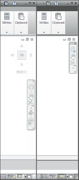
Figure 2-8: Navigation tools in AutoCAD (left) and AutoCAD LT (right).
Let your fingers do the talking: The command window
The infamous command window (or command line, or command prompt, or command area, whatever you want to call it), shown in Figure 2-9, is a throwback to the dark ages of AutoCAD. It puzzles newcomers and delights AutoCAD aficionados. Despite the promise of AutoCAD's heads-up Dynamic Input, for now at least, the hard truth is that you have to come to like — or at least tolerate — the command window if you want to become at all comfortable using AutoCAD.
![]()
Figure 2-9: Obey the command window.
You should cotton on and cozy up to the command window because it's still AutoCAD's primary communications conduit with you. AutoCAD sometimes displays prompts, warnings, and error messages in the command window that Dynamic Input doesn't show — there simply isn't room in the Dynamic Input tooltip to show as much information as you get at the command window. True, when using Dynamic Input, you can press the down-arrow key to see more options. But which is less efficient: moving your eyes down the screen to glance at the command window, or taking your eyes right off the screen to find the down-arrow key on your keyboard?
The key(board) to AutoCAD success
Despite (or is it because of?) AutoCAD's long heritage as the most successful CAD software for personal computers, newcomers are still astonished at the amount of typing they have to do. Some more-modern programs have much less dependency on the keyboard than AutoCAD, but as you get used to it, you'll find that no other input method gives you as much flexibility as pounding the ivories … oops, wrong keyboard!
Typing at your computer's keyboard is an efficient way to run some commands and the only way to run a few others. Instead of clicking a button or choosing from a menu, you can start a command by typing the command name and then pressing Enter. Even better, for most common commands, you can type the short form for a command name and press Enter. Most of the short forms (called aliases) of command names are just one or two letters — for example, L for the LINE command, and CP for the COPY command. Most people who discover how to use the aliases for the commands that they run most frequently find that their AutoCAD productivity improves noticeably. Even if you're not worried about increasing your productivity with this technique, several everyday commands are nowhere to be found on the Ribbon. If you want to run those commands, you have to type them!
AutoCAD 2012's new Autocomplete feature prompts one response: Why did it take so long? Most efficient AutoCAD jockeys use the keyboard. Many have customized their PGP files so the commands they use the most are one key tap away, but then there are those occasionally used commands, and those even more occasionally accessed system variables that don't get quite enough usage to justify a special shortcut. Now you can just start typing letters, and as soon as your command or variable appears, you can just click it. Hands up, everyone who'd rather type APPLY than APPLYGLOBALCAPACITIES!
Not all command aliases are as obvious as L for LINE: For example, CP for COPY or — believe it or not — T for MTEXT. To see a complete list of command aliases, look in the AutoCAD (or the AutoCAD LT) Program Parameters (PGP) file by going to the Manage tab and clicking Edit Aliases on the Customization panel. When Windows Notepad opens with the acad.pgp (or acadlt.pgp) file loaded, scroll down to the Sample Aliases for AutoCAD Commands section. I don't recommend changing anything here, but it's a good idea to print this file and pin up the aliases section over your desk.
After you start a command — whether from a Ribbon panel tool button, or by typing — the Dynamic Input tooltip and the command window are where AutoCAD prompts you with options for that command. You activate one of these options by typing the uppercase letter(s) in the option and then pressing Enter.
In many cases, you can activate a command's options by right-clicking in the drawing area and choosing the desired option from the menu that appears, instead of by typing the letter(s) for the option and pressing Enter.
 I like Dynamic Input. Really, I do. But sometimes it fights with normal command input, and that can make things really confusing. In the following chapters, I tell you when to be wary.
The following sequence demonstrates how you use the keyboard to run commands and to view and select options. If you have Dynamic Input toggled on, your results are going to be different from what I say, so I suggest you click Dynamic Input on the status bar to turn it off, temporarily at least. In the following steps, watch the command window, and pay attention to messages from AutoCAD:
- Type L and then press Enter.
AutoCAD starts the LINE command and displays the following prompt in the command window:
LINE Specify first point:
- Click a point anywhere in the drawing area.
The command window prompt changes to
Specify next point or [Undo]:
- Click another point anywhere in the drawing area.
AutoCAD draws the first line segment.
- Click a third point anywhere in the drawing area.
AutoCAD draws the second line segment and prompts
Specify next point or [Close/Undo]:
The command line now displays two options: Close and Undo, separated by a slash.
In this case, the Close and Undo options appear in brackets. The AutoCAD command line always displays command options in square brackets. To activate an option, type the letter(s) shown in uppercase and then press Enter. You can type the option letter(s) in lowercase or uppercase. - Type U and then press Enter.
AutoCAD undoes the second line segment.
- Type 3,2 (without any spaces) and then press Enter.
AutoCAD draws a new line segment to the point whose X coordinate is 3 and Y coordinate is 2.
- Click several more points anywhere in the drawing area.
AutoCAD draws additional line segments.
- Type X and then press Enter.
X isn't a valid option of the LINE command, so AutoCAD displays an error message and prompts you again for another point:
Point or option keyword required.
Specify next point or [Close/Undo]:
 Option keyword is programmer jargon for the letter(s) shown in uppercase that you type to activate a command option. This error message is AutoCAD's way of saying, “I don't understand what you mean by typing X. Either specify a point, or type a letter that I do understand.”
 - Type C and then press Enter.
AutoCAD draws a final line segment, which creates a closed figure and ends the LINE command. A blank command line returns, indicating that AutoCAD is ready for the next command:
Command:
- Press F2.
AutoCAD displays the AutoCAD Text Window, which is simply an enlarged, scrollable version of the command window, as shown in Figure 2-10.
The normal three-line command window usually shows you what you need to see, but occasionally you want to review a larger chunk of command-line history. (“What was AutoCAD trying to tell me a minute ago?!”) - Press F2 again.
AutoCAD closes the AutoCAD Text Window.
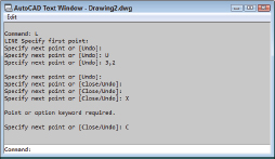
Figure 2-10: My, how you've grown: F2 expands the command line to a command text window.
Here are a few other tips and tricks for effective keyboarding:
- Use the Esc key to bail out of the current operation. Sometimes you might get confused about what you're doing in AutoCAD and/or what you're seeing in the command window or the Dynamic Input tooltip. If you need to bail out of the current operation, just press Esc one or more times until you see a blank command line — Command: at the bottom of the command window, with nothing after it. As in most other Windows programs, Esc is the cancel key. Unlike many other Windows programs, AutoCAD keeps you well informed of whether an operation is in progress. The blank command line indicates that AutoCAD is resting, waiting for your next command.
- Press Enter to accept the default action. Some command prompts include a default action in angled brackets. For example, the first prompt of the POLYGON command is
Enter number of sides <4>:
The default here is four sides, and you can accept it simply by pressing Enter. (That is, you don't have to type 4 first.)
- Command options appear in regular square brackets: [Close/Undo].
To activate a command option, type the letter(s) that appear in uppercase and then press Enter. The Dynamic Input tooltip doesn't display options in brackets; instead, you press the down-arrow key to display additional command options in rows next to the crosshairs.
- A default value or option appears in angled brackets: <4>.
To choose the default value or option, simply press Enter. Default values in angled brackets appear in both the Dynamic Input tooltip and the command-line prompts.
You don't always have to press Enter to forward your input to AutoCAD. Depending on what you're doing, you can often right-click and choose Enter from the top of the right-click menu. And most efficient of all, even for the most inept typists, you can use the spacebar as an Enter key — as long as you're not entering text. - Command options appear in regular square brackets: [Close/Undo].
- Watch the command line. You can discover a lot about how to use the command line simply by watching it after each action that you take. When you click a toolbar button or menu choice, AutoCAD displays the name of the command in the Dynamic Input tooltip and at the command line. If you're watching the command line, you'll absorb the command names more or less naturally.
When AutoCAD echoes commands automatically in response to your toolbar and menu clicks, it usually adds one or two extra characters to the front of the command name:
- AutoCAD usually puts an underscore in front of the command name: for example, _LINE instead of LINE. The underscore is an Autodesk programmers' trick that enables non-English language versions of AutoCAD to understand the English command names that are embedded in the menus.
- AutoCAD sometimes puts an apostrophe in front of the command name and any underscore (for example, '_ZOOM instead of ZOOM). The apostrophe indicates a transparent command; you can run a transparent command in the middle of another command without canceling the first command. For example, you can start the LINE command, run the ZOOM command transparently, and then pick up where you left off with the LINE command.
- Leave the command line in the default configuration. The command window, like most other parts of the AutoCAD screen, is resizable and movable. The default location (docked at the bottom of the AutoCAD screen) and size (three lines deep) work well for most people. Resist the temptation to mess with the command window's appearance — at least until you're comfortable with using the command line.
- Right-click in the command window for options. If you right-click in the command window, you see a menu with some useful choices, including Recent Commands — the last six commands that you ran.
- Press the up- and down-arrow keys to cycle through the stack of commands that you've used recently. This is another handy way to recall and rerun a command. Press the left- and right-arrow keys to edit the command line text that you've typed or recalled.
 AutoCAD uses two kinds of brackets when it prompts.
Most Windows users are familiar with Alt-key shortcuts. Press the Alt key in traditional Windows programs, and your menu bar lights up with one character of each menu item underlined. You type the underlined letter to open the menu or execute the command. AutoCAD's implementation of Microsoft's Fluent User Interface has an equivalent — KeyTips — which work in much the same way. In Figure 2-11, I've just pressed the Alt key. If I now tap the A key, the Annotate tab will open with a new set of KeyTips, and I can keep tapping the keys to execute a specific command.

Figure 2-11: Hold down the Alt key to display a kazillion KeyTips.
Keeping tabs on palettes
Palettes are refined (well-mannered) versions of dialog boxes. Unlike regular dialog boxes, which insist on your undivided attention as long as they're open, palettes stay discreetly in the background as you carry on with other tasks. AutoCAD still has many dialog boxes, but over the past several releases, quite a few former dialog boxes have been replaced by palettes.
AutoCAD 2012 contains more than a dozen palettes (more than a half-dozen in AutoCAD LT). Unless noted otherwise, you can open any of these palettes from the Palettes panel of the View tab. The more commonly used palettes are
- Properties, DesignCenter, and Content Explorer: These palettes are used to control object properties and find and display named objects (layers, blocks, and so on), and copy them between drawings. I cover the first two in Chapter 6.
- Tool Palettes: Each tool palette holds content (drawing symbols and hatch patterns) and/or commands (not regular AutoCAD commands — what would be the point? — but macros that make commands do specific things) instead of paints. You can create your own tool palettes, but the ones that come with AutoCAD contain dozens of symbols you can drag into your drawing — check 'em out!
- Sheet Set Manager: Provides tools for managing all of a project's drawings as a sheet set. I don't cover sheet sets in AutoCAD 2012 For Dummies.
- External References: Used to attach external files to the current drawing; file types include raster images, Drawing Web Format (DWF, or DWFx) files, PDF files, MicroStation DGN files, and other drawing files. I discuss attaching external reference files in Chapter 18.
- Markup Set Manager: Displays design and drafting review comments from users of Autodesk Design Review. For more information on markup sets, see the online help.
- QuickCalc: A handy pushbutton scientific calculator that hides out on the Home tab's Utilities panel. You'll know if you need this.
- Layer Properties Manager: The main control center for managing the layers on your drawing. The palettized Layer Properties Manager not only stays open while you're doing other things, but also applies any changes you make instantly in the drawing. The Layer Properties Manager can be found on the Layers panel of the Home tab.
Using the View and Home tabs is one way of opening palettes. Alternatively, several palettes have keyboard shortcuts. You can toggle these by pressing Ctrl+1 (Properties), Ctrl+2 (DesignCenter), Ctrl+3 (Tool Palettes), Ctrl+4 (Sheet Set Manager), Ctrl+7 (Markup Set Manager), or Ctrl+8 (QuickCalc).
Down the main stretch: The drawing area
After all these warm-up laps, you're probably itching for the main event — the AutoCAD drawing area. This is where you do your drawing, of course. In the course of creating drawings, you click points to specify locations and distances, click objects to select them for editing, and zoom and pan to get a better view of what you're working on.
Most of this book shows you how to interact with the drawing area, but you should know a few things up front.
Model space and paper space layouts
One of the initially disorienting things about AutoCAD is that finished drawings can be composed of objects drawn in different spaces, which AutoCAD indicates with either two status bar buttons, or two or more tabs at the bottom left of the drawing area:
- Model space: Where you create and modify the objects that represent things in the real world — walls, widgets, waterways, or whatever.
- Paper space: Where you create particular views of these objects for plotting, usually with a title block around them. Paper space comprises one or more layouts, each of which can contain a different arrangement of model space views and different title block information.
When you click the Model button on the status bar or the Model tab, you see pure, unadulterated model space, as shown in Figure 2-12. When you click the Layout button, you see a paper space layout, as shown in Figure 2-13. A completed layout usually includes one or more viewports, which are windows that display all or part of model space at a particular scale. A layout also usually includes a title block or other objects that exist only in the layout and don't appear when you click the Model tab. (Think of the viewport as a window looking into model space and the title block as a frame around the window.) Thus, a layout displays model space and paper space objects together, and AutoCAD lets you draw and edit objects in either space. See Chapter 5 for information about creating paper space layouts and Chapter 16 for the lowdown on plotting them.

Figure 2-12: A building model ready for editing in model space.
When a layout is current, you can move the crosshairs back and forth between model space and paper space while remaining in the layout. You can't be in both spaces at the same time, however; if paper space is current, you can click directly on top of a model space object, but it won't be selected. Similarly, if model space is current, you can't select anything in paper space. To move between the two spaces, double-click inside a viewport to switch to model space or outside a viewport to switch to paper space.
This back-and-forth double-clicking is necessary only when you're drawing things while viewing one of the paper space layouts or adjusting the view of the drawing objects within the viewport. In practice, you probably won't draw very much using this method. Instead, you'll do most of your drawing on the Model tab, and after you've set up a paper space layout, click its layout tab only when you want to plot.

Figure 2-13: Freshly laid out in paper space.
Drawing on the drawing area
Here are a few other things to know about the AutoCAD drawing area:
- Efficient, confident use of AutoCAD requires that you continually glance from the drawing area to the command window (to see those all-important prompts!) and then back up to the drawing area. This sequence is not a natural reflex for most people, and that's why the Dynamic Input tooltip at the crosshairs was introduced. But you still get information from the command line that you don't get anywhere else. Get in the habit of looking at the command line after each action that you take.
- Clicking at random in the drawing area is not quite as harmless in AutoCAD as it is in many other Windows programs. When you click in the AutoCAD drawing area, you're almost always performing some action — usually specifying a point or selecting objects for editing. Feel free to experiment, but look at the command line after each click. If you get confused, press Esc a couple of times to clear the current operation and return to the naked command prompt.
- In most cases, you can right-click in the drawing area to display a menu with some options for the current situation.